содержание .. 1082 1083 1084 1085 ..
Nissan Tiida C11. Manual - part 1084
MWI-26
< COMPONENT DIAGNOSIS >
POWER SUPPLY AND GROUND CIRCUIT
POWER SUPPLY AND GROUND CIRCUIT
COMBINATION METER
COMBINATION METER : Diagnosis Procedure
INFOID:0000000001374688
1.
CHECK FUSES
Check for blown combination meter fuses.
Is the inspection result normal?
YES
>> GO TO 2
NO
>> If fuse is blown, be sure to eliminate cause of malfunction before installing new fuse.
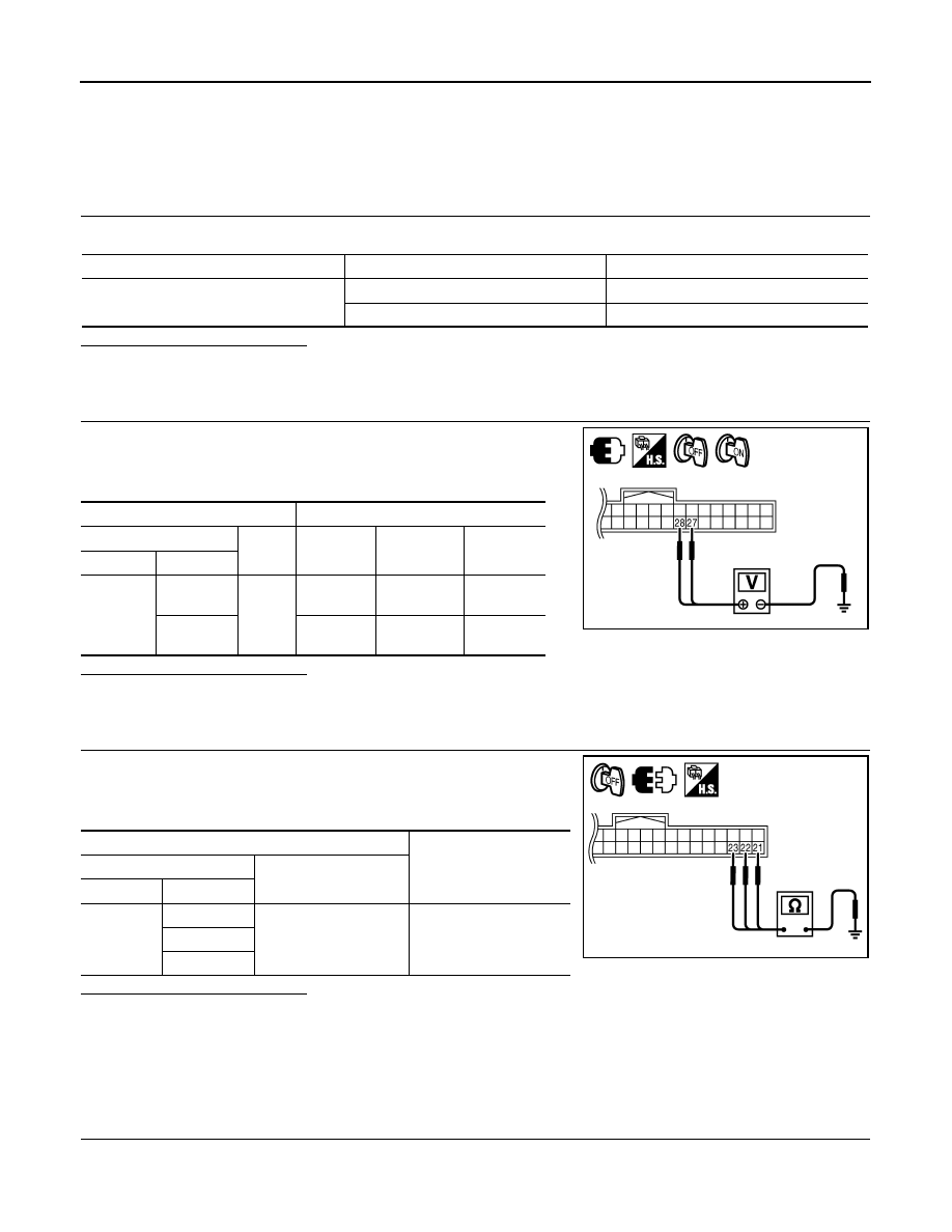
2.
POWER SUPPLY CIRCUIT CHECK
1.
Disconnect combination meter connector M24.
2.
Check voltage between combination meter harness connector
M24 terminals 27, 28 and ground.
Is the inspection result normal?
YES
>> GO TO 3
NO
>> Check harness for open between combination meter and fuse.
3.
GROUND CIRCUIT CHECK
1.
Turn ignition switch OFF.
2.
Check continuity between combination meter harness connector
M24 terminals 21, 22, 23 and ground.
Is the inspection result normal?
YES
>> Inspection End.
NO
>> Repair harness or connector.
BCM (BODY CONTROL MODULE)
BCM (BODY CONTROL MODULE) : Diagnosis Procedure
INFOID:0000000001713117
1.
CHECK FUSES AND FUSIBLE LINK
Check that the following fuses and fusible link are not fusing.
Unit
Power source
Fuse No.
Combination meter
Battery 13
Ignition switch ON or START
3
Terminals
Ignition switch position
(+)
(–)
OFF
ON
START
Connector
Terminal
M24
27
Ground
Battery
voltage
Battery
voltage
Battery
voltage
28
0V
Battery
voltage
Battery
voltage
PKIC0700E
Terminals
Continuity
(+)
(–)
Connector
Terminal
M24
21
Ground
Yes
22
23
PKIC0701E