Nissan Tiida C11. Manual - part 89


  Главная      Nissan     Nissan Tiida C11 - Service Manual


поиск по сайту            


содержание   ..  87  88  89  90   ..


Nissan Tiida C11. Manual - part 89


BRC-122

< COMPONENT DIAGNOSIS >

[ESP/TCS/ABS]

C1113, C1145, C1146 YAW RATE/SIDE/DECEL G SENSOR

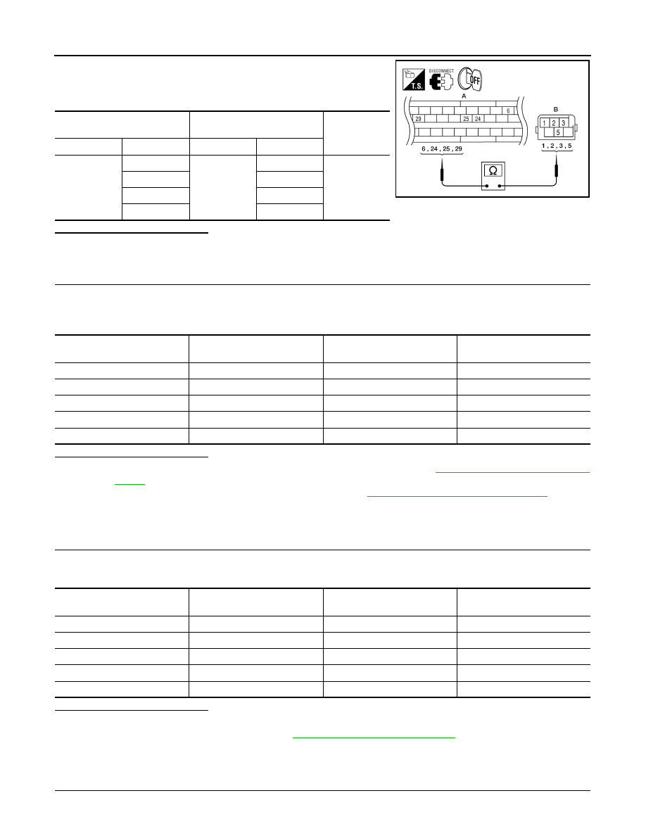
Check continuity between the ABS actuator and electric unit (control
unit) connector E125 (A) and the yaw rate/side/decel G sensor con-
nector M108 (B).

Is the inspection result normal?

YES

>> GO TO 3

NO

>> Repair or replace as necessary.

3.

YAW RATE/SIDE/DECEL G SENSOR INSPECTION

1.

Connect the yaw rate/side/decel G sensor connector M108 and ABS actuator and electric unit (control
unit) connector E125.

2.

Use “DATA MONITOR” to check if the yaw rate/side/decel G sensor signals are normal. 

Is the inspection result normal?

YES

>> Replace the ABS actuator and electric unit (control unit). Refer to 

BRC-184, "Removal and Instal-

lation"

.

NO

>> Replace the yaw rate/side/decel G sensor. Refer to 

BRC-185, "Removal and Installation"

.

Component Inspection

INFOID:0000000001731107

1.

CHECK DATA MONITOR

Select “YAW RATE SEN”, “SIDE G-SENSOR”, “DECEL G-SEN” in “DATA MONITOR” and check yaw rate/
side/decel G sensor signal.

Is the inspection result normal?

YES

>> INSPECTION END

NO

>> Go to diagnosis procedure. Refer to 

BRC-121, "Diagnosis Procedure"

.

Special Repair Requirement

INFOID:0000000001731108

1.

ADJUSTMENT OF STEERING ANGLE SENSOR NEUTRAL POSITION

ABS actuator and electric unit 

(control unit)

Yaw rate/side/decel G sensor

Continuity

Connector

Terminal

Connector

Terminal

A: E125

6

B: M108

3

Yes

24

5

25

1

29

2

AWFIA0024ZZ

Vehicle condition

YAW RATE SEN

(DATA MONITOR)

SIDE G-SENSOR

(DATA MONITOR)

DECEL G-SEN

(DATA MONITOR)

Stopped

-4 to +4 deg/s

-1.1 to +1.1 m/s

-0.11 G to +0.11 G

Turning right

Negative value

Negative value

-

Turning left

Positive value

Positive value

-

Speed up

-

-

Negative value

Speed down

-

-

Positive value

C1113, C1145, C1146 YAW RATE/SIDE/DECEL G SENSOR

BRC-123

< COMPONENT DIAGNOSIS >

[ESP/TCS/ABS]

C

D

E

G

H

I

J

K

L

M

A

B

BRC

N

O

P

Always perform neutral position adjustment for the steering angle sensor when replacing the ABS actuator
and electric unit (control unit). Refer to 

BRC-90, "ADJUSTMENT OF STEERING ANGLE SENSOR NEUTRAL

POSITION : Description"

.

>> GO TO 2

2.

CALIBRATION OF DECEL G SENSOR

Always perform calibration of decel G sensor when replacing the ABS actuator and electric unit (control unit).
Refer to 

BRC-91, "CALIBRATION OF DECEL G SENSOR : Description"

.

>> END

BRC-124

< COMPONENT DIAGNOSIS >

[ESP/TCS/ABS]

C1115 WHEEL SENSOR

C1115 WHEEL SENSOR

Description

INFOID:0000000001731109

When the sensor rotor rotates, the magnetic field changes. It converts the magnetic field changes to current
signals (rectangular wave) and transmits them to the ABS actuator and electric unit (control unit). 

DTC Logic

INFOID:0000000001731110

DTC DETECTION LOGIC

DTC CONFIRMATION PROCEDURE

1.

CHECK SELF-DIAGNOSIS RESULTS

Check the self-diagnosis results.

Is above displayed on the self-diagnosis display?

YES

>> Proceed to diagnosis procedure. Refer to 

BRC-41, "Diagnosis Procedure"

.

NO

>> INSPECTION END

Diagnosis Procedure

INFOID:0000000001731111

CAUTION:

Do not check between wheel sensor terminals.

INSPECTION PROCEDURE

1.

CONNECTOR INSPECTION

Disconnect the ABS actuator and electric unit (control unit) connector E125 and wheel sensor of malfunction-
ing code. 
Check the terminals for deformation, disconnection, looseness or damage.

Is the inspection result normal?

YES

>> GO TO 2

NO

>> Repair or replace as necessary.

2.

CHECK WHEEL SENSOR OUTPUT SIGNAL

1.

Connect ABS active wheel sensor tester (J-45741) to wheel sensor using appropriate adapter.

2.

Turn on the ABS active wheel sensor tester power switch.
NOTE:
The green POWER indicator should illuminate. If the POWER indicator does not illuminate, replace the
battery in the ABS active wheel sensor tester before proceeding.

3.

Spin the wheel of the vehicle by hand and observe the red SENSOR indicator on the ABS active wheel
sensor tester. The red SENSOR indicator should flash on and off to indicate an output signal.
NOTE:
 If the red SENSOR indicator illuminates but does not flash, reverse the polarity of the tester leads and
retest.

Does the ABS active wheel sensor tester detect a signal?

YES

>> GO TO 3

NO

>> Replace the wheel sensor. Refer to 

BRC-182, "Removal and Installation"

.

3.

CHECK TIRES

DTC

Display item

Malfunction detected condition

Possible cause

C1115

ABS SENSOR
[ABNORMAL SIGNAL]

When wheel sensor input signal is malfunctioning.

• Harness or connector
• Wheel sensor
• ABS actuator and electric unit 

(control unit)

Self-diagnosis results

ABS SENSOR [ABNORMAL SIGNAL]

C1115 WHEEL SENSOR

BRC-125

< COMPONENT DIAGNOSIS >

[ESP/TCS/ABS]

C

D

E

G

H

I

J

K

L

M

A

B

BRC

N

O

P

Check for inflation pressure, wear and size of each tire.

Are tire pressure and size correct and is tire wear within specifications?

YES

>> GO TO 4

NO

>> Adjust tire pressure or replace tire(s).

4.

CHECK WHEEL BEARINGS

Check wheel bearing axial end play. Refer to 

FAX-5, "On-Vehicle Inspection and Service"

 (front) or 

RAX-5,

"On-Vehicle Inspection and Service"

 (rear).

Is the inspection result normal?

YES

>> GO TO 5

NO

>> Repair or replace as necessary. Refer to 

FAX-7, "Removal and Installation"

 (front) or 

RAX-6,

"Removal and Installation"

 (rear).

5.

CHECK WIRING HARNESS FOR SHORT CIRCUIT

1.

Disconnect ABS actuator and electric unit (control unit) connec-
tor and wheel sensor connector of malfunction code No.

2.

Check continuity between wheel sensor harness connector ter-
minals and ground.

Is the inspection result normal?

YES

>> GO TO 6

NO

>> Repair the circuit.

6.

CHECK WIRING HARNESS FOR OPEN CIRCUIT

1.

Check continuity between ABS actuator and electric unit (control unit) harness connector E125 and the
malfunctioning wheel sensor harness connector E18, E117, C10, or C11.

Is the inspection result normal?

YES

>> Replace the ABS actuator and electric unit (control unit). Refer to 

BRC-184, "Removal and Instal-

lation"

.

NO

>> Repair the circuit.

Component Inspection

INFOID:0000000001731112

1.

CHECK DATA MONITOR

On “DATA MONITOR”, select “FR LH SENSOR”, “FR RH SENSOR”, “RR LH SENSOR”, and “RR RH SEN-
SOR”, and check the vehicle speed.

Continuity should not exist.

WFIA0343E

Wheel sensor

ABS actuator and 

electric unit (control unit)

Wheel sensor

Continuity

Connector

Terminal

Connector

Terminal

Front LH

E125

45

E18

1

Yes

46

2

Front RH

34

E117

1

33

2

Rear LH

37

C11

2

36

1

Rear RH

42

C10

2

43

1

Wheel sensor

Vehicle speed (DATA MONITOR)


содержание   ..  87  88  89  90   ..