содержание .. 55 56 57 58 ..
Nissan Tiida C11. Manual - part 57
FRONT DISC BRAKE
BR-35
< DISASSEMBLY AND ASSEMBLY >
C
D
E
G
H
I
J
K
L
M
A
B
BR
N
O
P
Check sliding pins, sliding pin bolts and sliding pin boots for wear, damage, and cracks. Replace applicable
part as necessary.
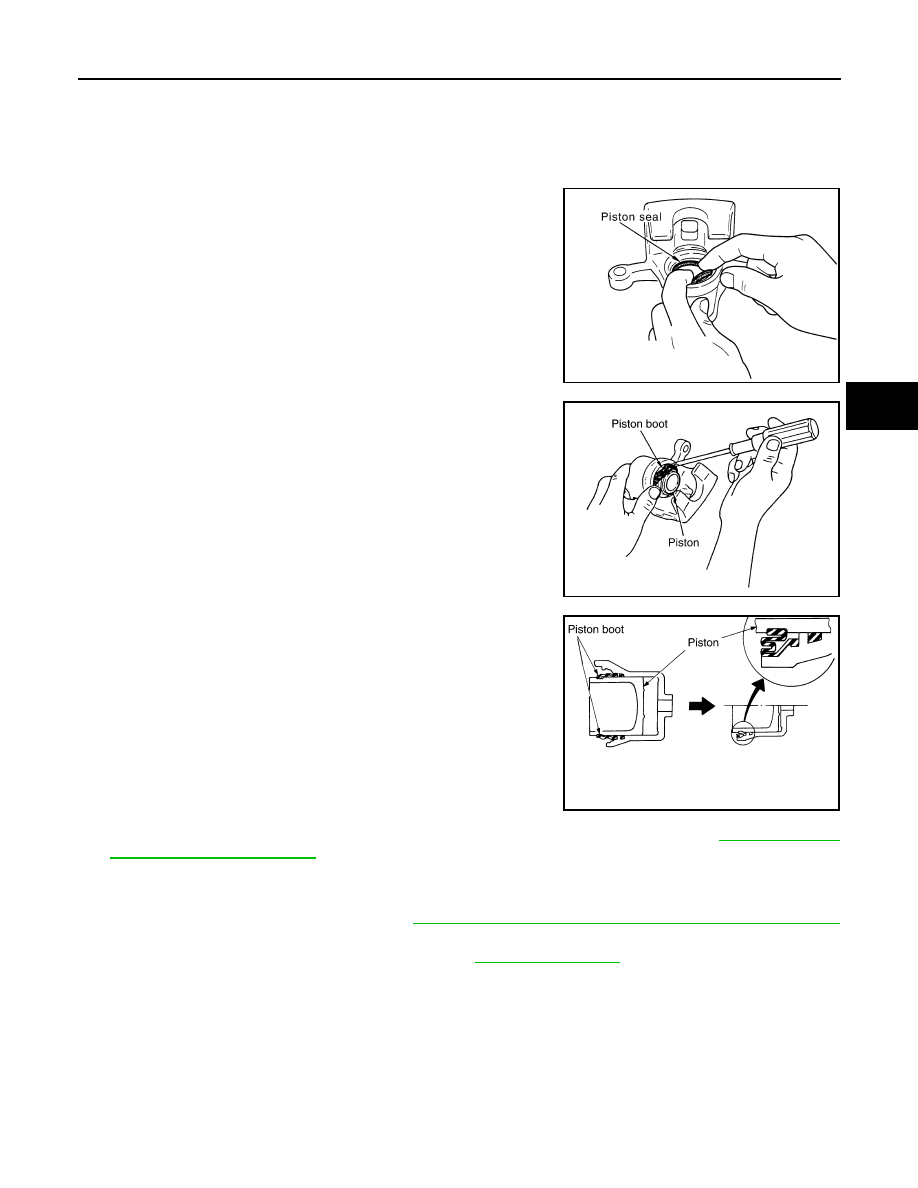
ASSEMBLY
CAUTION:
When assembling, use only specified rubber lubricant.
1.
Apply polyglycol ether based lubricant to new piston seal and
install them to cylinder body.
2.
Apply rubber grease to piston boot and apply brake fluid to pis-
ton. Cover the piston end with piston boot, and install cylinder-
side lip on piston boot properly into groove on cylinder body.
3.
Press piston into cylinder body by hand to assemble piston-side
lip on piston boot properly into a groove on piston.
CAUTION:
Press piston evenly and change pressing point to prevent
inner wall of cylinder from being rubbed.
4.
Install sliding pins and sliding pin boots to the torque member.
5.
If pads, shims and pad retainers were removed, install them to torque member. Refer to
and Installation of Brake Pad"
6.
Install cylinder body to torque member.
7.
Install sliding pin bolts.
8.
Install caliper assembly to vehicle. Refer to
BR-25, "Removal and Installation of Brake Caliper Assembly"
.
9.
Tighten sliding pin bolts to specified torque. Refer to
.
DISC ROTOR INSPECTION
Visual Inspection
Check surfaces of disc rotor for uneven wear, cracks, and serious damage. Replace applicable part as neces-
sary.
Runout Inspection
1.
Using wheel nuts, secure disc rotor to wheels hub 2 or more positions.
SFIA2278E
SFIA3074E
SFIA2279E