содержание .. 56 57 58 59 ..
Nissan Tiida C11. Manual - part 58
REAR DISC BRAKE
BR-39
< DISASSEMBLY AND ASSEMBLY >
C
D
E
G
H
I
J
K
L
M
A
B
BR
N
O
P
5.
Attach the sliding pin bolt and sliding pin boot to the torque member.
6.
Apply PBC (Poly Butyl Cuprysil) grease or silicone-based grease to the rear of the pad and to both sides
of the shim, and attach the inner shim and shim cover to the inner pad, and the outer shim and outer shim
cover to the outer pad.
7.
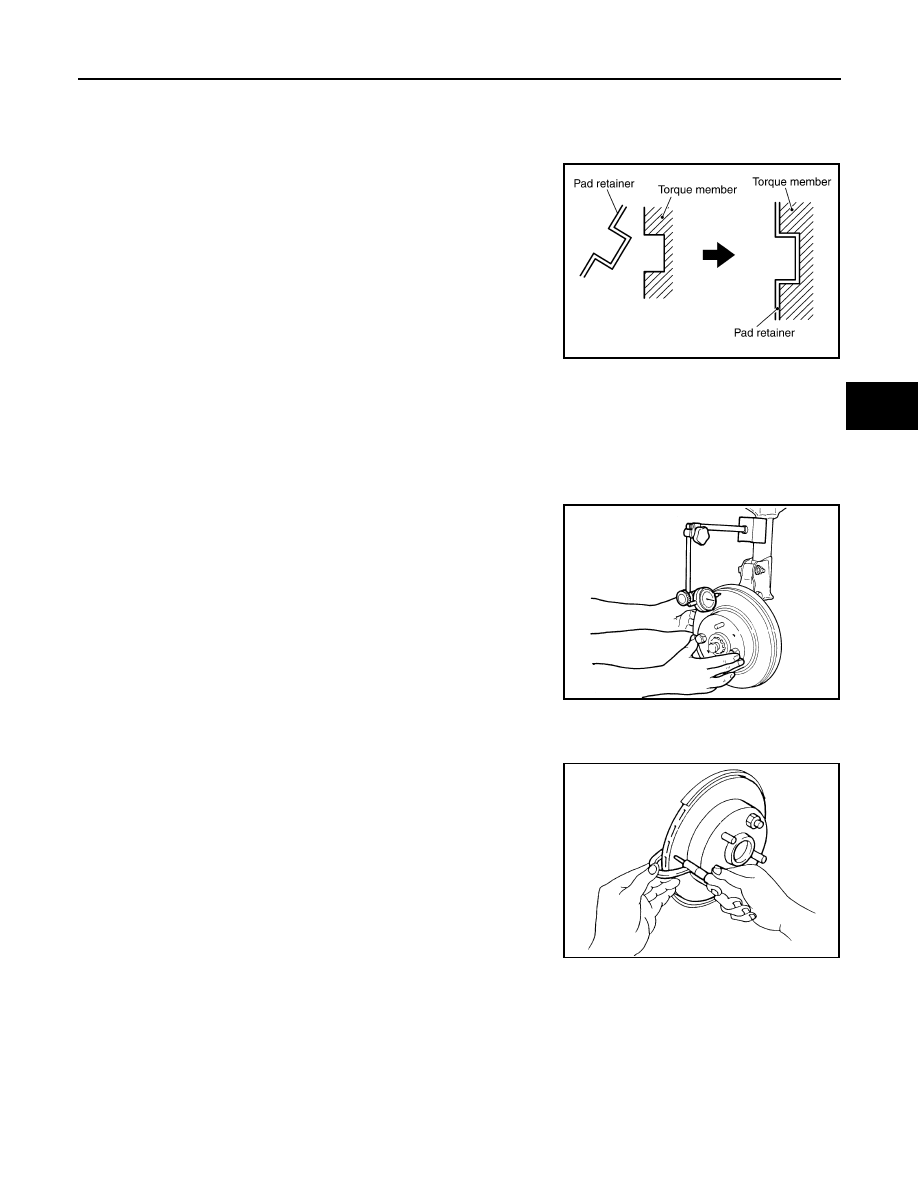
Attach the pad retainer and pad to the torque member.
CAUTION:
When attaching the pad retainer, attach it firmly so that it
does not float up higher than the torque member, as shown
in the figure.
8.
After assembling shims and shim covers to pad, install it to the
torque member.
9.
Install cylinder body. Tighten sliding pin bolts to the specified
torque.
DISC ROTOR INSPECTION
Visual Inspection
Check surface of the disc rotor for uneven wear, cracks, and serious damage. If any non-standard condition is
detected, replace applicable part.
Runout Inspection
1.
Using wheel nuts, fix disc rotor to the wheel hub in two or more positions.
2.
Inspect runout using a dial gauge.
CAUTION:
Before measuring, make sure the axle endplay is 0 mm (0
in).
3.
If runout is outside the limit, find the minimum runout point by
shifting mounting positions of the disc rotor and wheel hub by
one hole.
Thickness Inspection
Using a micrometer, check thickness of the disc rotor. If thickness is
not within specification, replace disc rotor.
PFIA0273E
Measurement position
: At a point 10 mm (0.39 in)
from outer edge of the disc.
Runout limit (with it at-
tached to the vehicle)
: 0.07 mm (0.0028 in) or less
BRA0013D
Standard thickness
: 9.0 mm (0.350 in)
Minimum thickness
: 8.0 mm (0.310 in)
Maximum uneven wear
(measured at 8 positions)
: 0.015 mm (0.0006 in) or
less
SBR020B