содержание .. 53 54 55 56 ..
Nissan Tiida C11. Manual - part 55
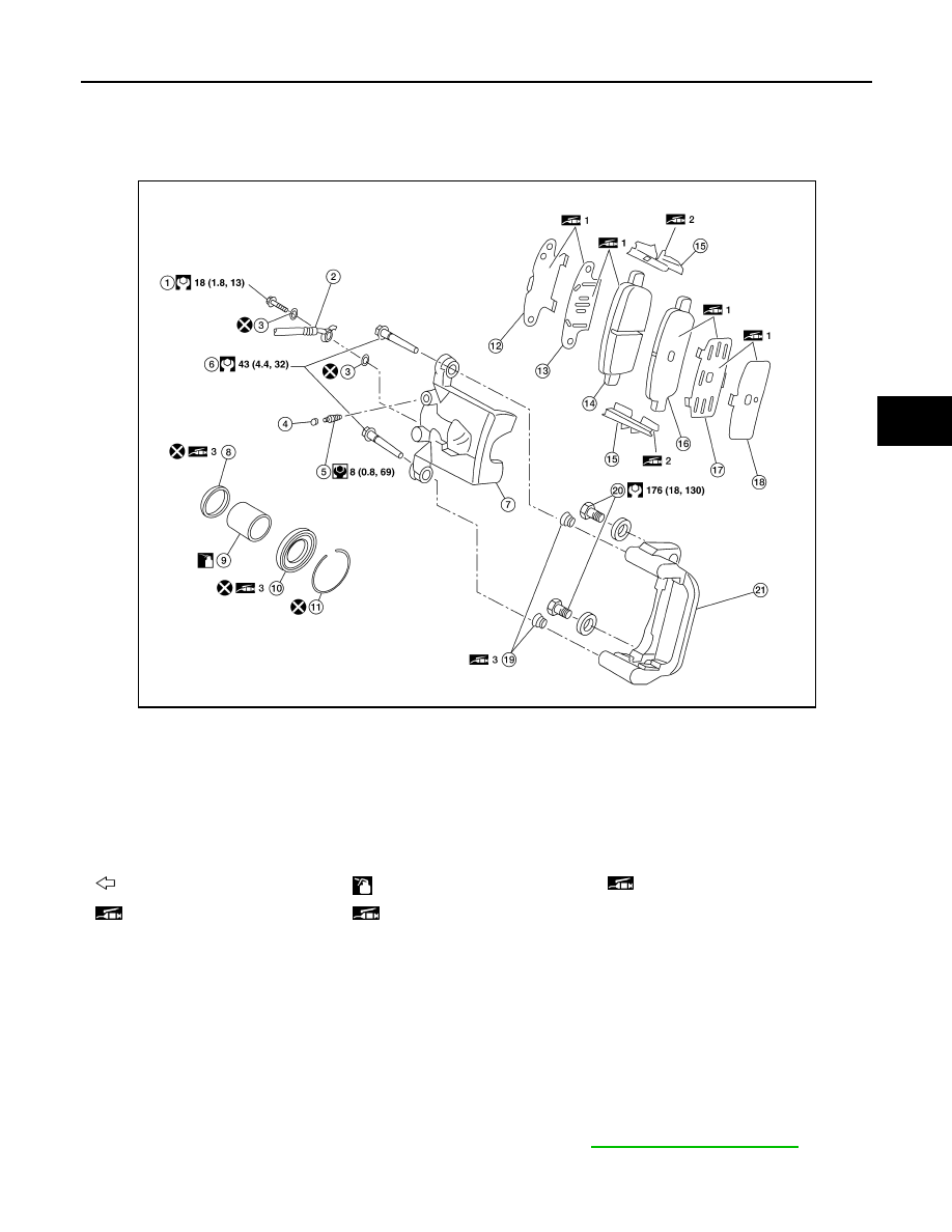
REAR DISC BRAKE
BR-27
< ON-VEHICLE REPAIR >
C
D
E
G
H
I
J
K
L
M
A
B
BR
N
O
P
REAR DISC BRAKE
Component
INFOID:0000000001724666
WARNING:
Clean dust on caliper and brake pad with a vacuum dust collector. Do not blow with compressed air.
CAUTION:
• While removing cylinder body, never depress the brake pedal because the piston will pop out.
• It is not necessary to remove bolts on torque member and brake hose except for disassembly or
replacement of the cylinder body. In this case, hang cylinder body with a wire so that brake hose is
not under tension.
• Do not damage piston boot.
• Always replace shims and shim covers as a set when replacing brake pads.
• Keep the rotor clean of brake fluid.
• Burnish the brake contact surfaces when refinishing or replacing brake rotors, after replacing pads
or linings, or if a soft pedal occurs at very low mileage. Refer to
1.
Connecting bolt
2.
Brake hose
3.
Copper washer
4.
Cap
5.
Air bleeder
6.
Sliding pin
7.
Cylinder body
8.
Piston seal
9.
Piston
10.
Piston boot
11.
Retaining ring
12.
Inner shim cover
13.
Inner shim
14. Inner pad
15.
Pad retainer
16.
Outer pad
17. Outer shim
18.
Outer shim cover
19.
Sliding pin boot
20. Torque member bolts
21.
Torque member
: Front
: Brake fluid
1: M-77 grease
2: M7439 grease
3: Rubber grease
AWFIA0085GB