содержание .. 52 53 54 55 ..
Nissan Tiida C11. Manual - part 54
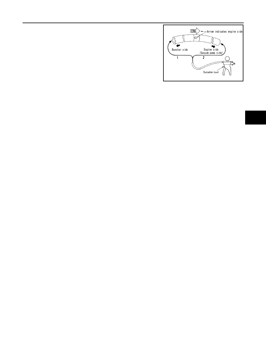
VACUUM LINES
BR-23
< ON-VEHICLE REPAIR >
C
D
E
G
H
I
J
K
L
M
A
B
BR
N
O
P
Use a handy vacuum pump to check.
Replace vacuum hose with the check valve as a set if damage or
deformation is present at the vacuum hose.
When connected to booster side (1):
Vacuum decrease should be within 1.3 kPa
(10 mmHg, 0.39 inHg) for 15 seconds under
a vacuum of –66.7 kPa (–500 mmHg, –19.69
inHg)
When connected to engine side (2):
No vacuum will be applied
SFIA0210E