содержание .. 50 51 52 53 ..
Nissan Tiida C11. Manual - part 52
BRAKE TUBE AND HOSE
BR-15
< ON-VEHICLE REPAIR >
C
D
E
G
H
I
J
K
L
M
A
B
BR
N
O
P
1.
Drain brake fluid. Refer to
.
2.
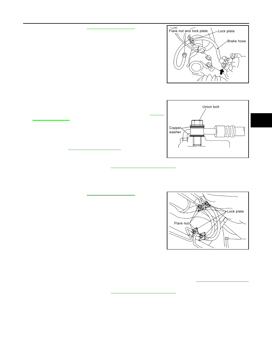
Using a flare nut wrench, remove brake tube from brake hose.
3.
Remove union bolt, and remove brake hose from caliper assem-
bly.
4.
Remove lock plate, and remove brake hose from vehicle.
INSTALLATION
1.
Assemble union bolt and copper washers to brake hose.
2.
Position the L-shape metal fitting of the brake hose to the brake
caliper assembly positioning hole.
3.
Tighten union bolt to the specified torque. Refer to
.
4.
Connect brake hose to brake tube on vehicle, and temporarily
tighten flare nut by hand as much as possible.
5.
Secure it with lock plate.
6.
Tighten flare nut to the specified torque with a flare nut torque
wrench. Refer to
.
7.
Install brake hose to vehicle, and tighten nuts to the specified
torque.
8.
Bleed air from brake system. Refer to
.
Rear Brake Tube and Hose
INFOID:0000000001716984
REMOVAL
1.
Drain brake fluid. Refer to
.
2.
Using a flare nut wrench, remove brake tube from brake hose.
3.
Remove lock plate, and remove brake hose from vehicle.
INSTALLATION
1.
Connect brake hose to brake tube on vehicle, and temporarily tighten flare nut by hand as much as possi-
ble.
2.
Secure it to bracket with lock plate.
3.
Tighten flare nut to the specified torque with a flare nut torque wrench. Refer to
.
4.
Bleed air from brake system. Refer to
.
Inspection After Installation
INFOID:0000000001716985
CAUTION:
• Always disassemble the parts and retighten their fittings, if a brake fluid leak is detected. Replace
applicable part with a new one, if damaged part is detected.
• If leak is detected at the connections, retighten it or replace the damaged part.
SFIA1118E
SFIA1137E
SFIA1120E