содержание .. 49 50 51 52 ..
Nissan Tiida C11. Manual - part 51
REAR DISC BRAKE
BR-11
< ON-VEHICLE MAINTENANCE >
C
D
E
G
H
I
J
K
L
M
A
B
BR
N
O
P
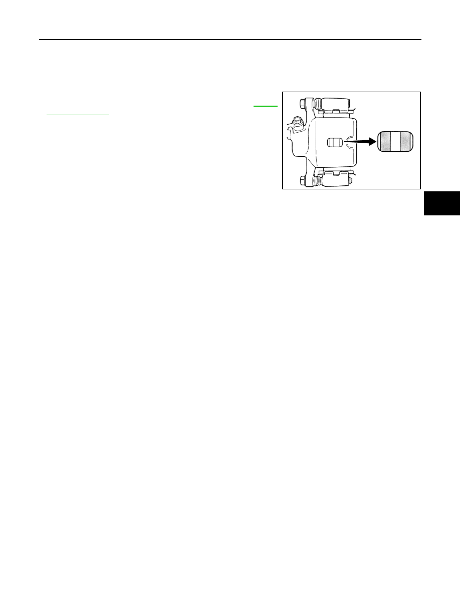
REAR DISC BRAKE
Inspection
INFOID:0000000001724674
PAD WEAR INSPECTION
• Inspect pad thickness through inspection hole on cylinder body.
Use a ruler or caliper for inspection if necessary. Refer to
.
BRA0010D