Mitsubishi Outlander PHEV (2022 year). Manual in english - page 12

Rear Cross Traffic Alert (RCTA) (if so equipped)
WARNING
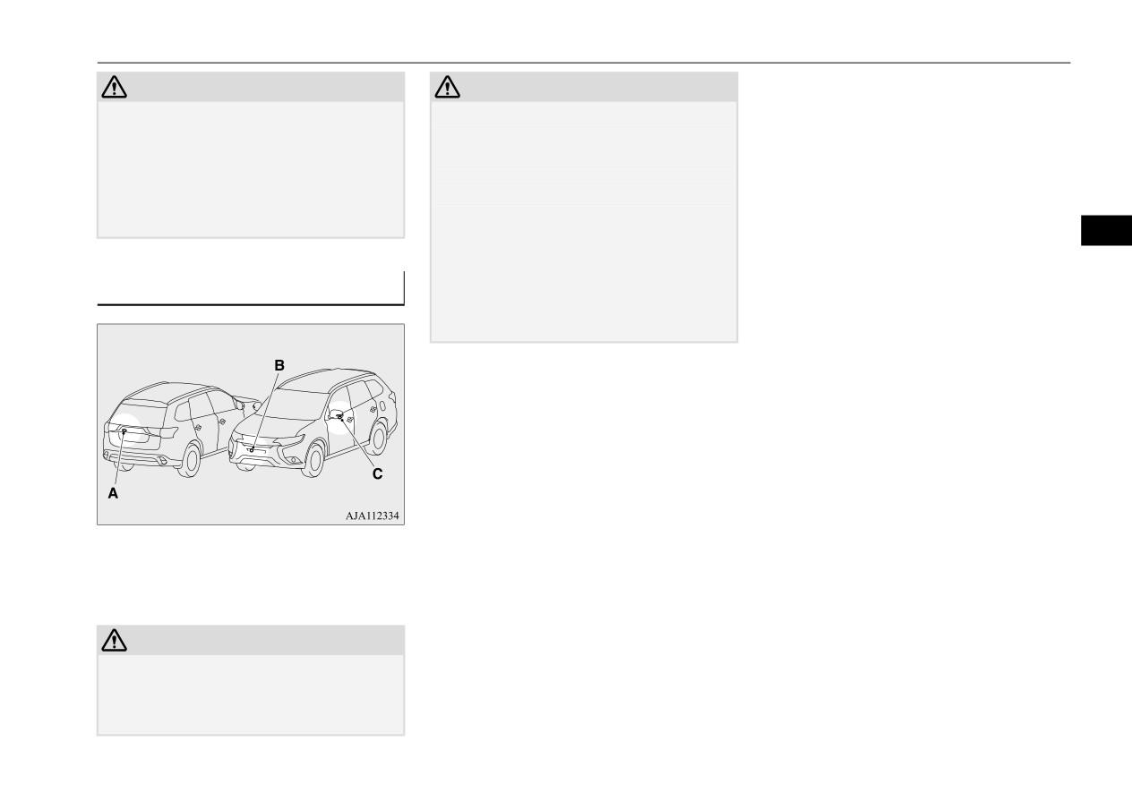
'HWHFWLRQ DUHDV
CAUTION
z 1HYHU UHO\ VROHO\ RQ WKH 5&7$ ZKHQ EDFN
• When a approaching vehicle speed is
LQJ XS
7KH 5&7$ LV DQ DLG V\VWHP
,W LV
The detection area is shown as illustrated.
approximately 4 mph (7 km/h) or less.
QRW D VXEVWLWXWH IRU \RXU VDIH DQG FDUHIXO
• If the sensor detection area is blocked by a
GULYLQJ $OZD\V FKHFN YLVXDOO\ EHKLQG DQG
nearby object, such as wall or parked vehi-
DOO DURXQG \RXU YHKLFOH IRU RWKHU YHKLFOHV
cle.
SHUVRQV DQLPDOV RU REVWUXFWLRQV
• When a vehicle is approaching from
7KH SHUIRUPDQFH RI WKH 5&7$ PD\ YDU\
straight behind your vehicle.
5
GHSHQGLQJ RQ GULYLQJ WUDIILF DQG RU VXU
• When your vehicle is exiting from an
URXQGLQJ FRQGLWLRQV
angled parking spot.
NOTE
z The Blind Spot Warning lights in the outside
rearview mirrors on both sides will blink,
even when only one vehicle is approaching
from one side.
• Immediately after the RCTA has been
turned on.
• Immediately after the operation mode of
the power switch has been put in ON.
• When the bumper surface around the sensor
is covered with dirt, snow and ice, etc.
• When the sensor becomes extremely hot or
cold, such as after the vehicle has been
CAUTION
parked for a prolonged time under the blaz-
z In certain situations, the RCTA may not
ing sun or in cold weather.
detect a vehicle in the detection areas. Some
z If the bumper has experienced an impact, the
of these situations include;
sensor may have been damaged and the
• When the reversing speed of your vehicle is
RCTA may not function properly. Have the
approximately 11 mph (18 km/h) or higher.
vehicle inspected at a certified Mitsubishi
EV dealer.
Features and controls
5-115
Rear Cross Traffic Alert (RCTA) (if so equipped)
7R RSHUDWH
1. Press the BSW switch while the operation
mode of the power switch is put in ON.
(Refer to “Blind Spot Warning (BSW): To
operate” on page 5-110.)
2. When the select position is put in the “R”
(REVERSE) position, the RCTA will
5
operate.
NOTE
z Set the RCTA to OFF when towing.
z The Blind Spot Warning light in the outside
rearview mirror may not be visible due to
strong direct sunlight or the glare from the
headlights of vehicles behind you during
night driving.
:KHQ D SUREOHP LV GHWHFWHG LQ
WKH V\VWHP
If the system detects a problem, a warning is
displayed on the information screen in the
multi-information display.
Refer to “Blind Spot Warning (BSW): Sys-
tem problem warning” on page 5-111.
5-116
Features and controls
Rear Cross Traffic Alert (RCTA) (if so equipped)
*HQHUDO LQIRUPDWLRQ
N00594000169
)RU YHKLFOHV VROG LQ 8 6
$
5
Features and controls
5-117

Lane Departure Warning System (LDW) (if so equipped)
)RU YHKLFOHV VROG LQ &DQDGD
/DQH 'HSDUWXUH :DUQLQJ
Applicable law: RSS-210
6\VWHP /': LI VR HTXLSSHG
This device contains licence-exempt trans-
N00577900118
mitter(s)/receiver(s) that comply with Innova-
The Lane Departure Warning system (LDW)
tion, Science and Economic Development
is a driving aid system to help prevent unin-
Canada’s licence-exempt RSS(s). Operation
tentional lane departure. The LDW is
is subject to the following two conditions:
designed to read lane markers by using a sen-
5
1. This device may not cause interference.
sor (A) under certain conditions. The LDW
2. This device must accept any interference,
will give you both visual and audible warn-
including interference that may cause
ings when your vehicle is leaving or has left
undesired operation of the device.
the lane.
Radiofrequency radiation exposure informa-
tion:
This equipment complies with radiation
exposure limits set forth for an uncontrolled
environment. This equipment should be
installed and operated with minimum dis-
tance of 20 cm between the radiator and your
body.
5-118
Features and controls

Lane Departure Warning System (LDW) (if so equipped)
To turn on the LDW, press the LDW switch.
2SHUDWLRQ RI WKH /':
The the “LDW” indicator will appear on the
N00581100078
information screen of the multi information
display.
The LDW, when turned ON, is capable of
recognizing the lane in which your vehicle is
travelling and issuing an audible warning
when your vehicle begins to leave that travel
lane. When operating, the “LDW” indicator
on the multi-information display will be
5
changed to
indicator (green). The LDW
will not operate, however, and the “LDW”
indicator will be appeared if any of following
WARNING
conditions have occurred:
z
1HYHU UHO\ VROHO\ RQ WKH /': 7KH /': LV
To turn off the LDW, press the LDW switch.
QRW D FROOLVLRQ DYRLGDQFH V\VWHP DQG LV QRW
z The vehicle speed is less than approxi-
The “LDW” indicator on the information
D VXEVWLWXWH IRU \RXU VDIH DQG FDUHIXO GULY
mately 38 mph (60 km/h).
screen of the multi information display will
LQJ
z The turn signal lever is being operated or
then go out.
z
%HIRUH XVLQJ WKH /': UHDG WKLV HQWLUH
has been operated in the past 7 seconds.
To return the LDW to “ON”, press the LDW
VHFWLRQ WR XQGHUVWDQG WKH OLPLWDWLRQV RI
z The hazard warning light is being oper-
WKLV V\VWHP
)DLOXUH WR IROORZ LQVWUXFWLRQV
switch again.
ated or has been operated in the past 7
FRXOG UHVXOW LQ DQ DFFLGHQW
seconds.
7R WXUQ RQ RII WKH /':
NOTE
z The LDW is turned on when the vehicle is
shipped from the factory.
z The currently selected LDW setting (on or
off) is stored even when the ignition switch
is turned to the “OFF” position or the opera-
tion mode is put in OFF.
Features and controls
5-119

Lane Departure Warning System (LDW) (if so equipped)
/DQH GHSDUWXUH ZDUQLQJ
WARNING
CAUTION
N00581200053
z
7KH /': PD\ QRW RSHUDWH FRUUHFWO\ LQ WKH
z
To maintain proper function of the LDW:
While the “LDW” indicator in the informa-
IROORZLQJ VLWXDWLRQV DQG WKH /': PD\ QRW
• Always keep the windshield and the head-
tion display is lit in green, if your vehicle is
JLYH ZDUQLQJV RU PD\ JLYH IDOVH ZDUQLQJV
lights clean.
leaving or has left the lane, a buzzer will
:KHQ ODQH PDUNHUV DUH QRW FOHDUO\ YLVL
• Do not put anything, such as a sticker, on
sound intermittently, “LANE DEPARTURE”
EOH GXH WR UDLQ VQRZ IRJ GDUN DUHD HWF
the front windshield in front of the sensor.
will appear in the information display and
:KHQ WKH URDG VXUIDFH LV VKLQ\
• Avoid applying a shock or load to the sen-
:KHQ ROG ODQH PDUNHUV UHPDLQ RQ WKH
sor.
5
the
indicator will be flashing in amber.
URDG VXUIDFH
• Do not attempt to detach or disassemble the
:KHQ WKH ODQH PDUNHUV DUH GRXEOH OLQHV
sensor.
RU WKH VKDSH RI WKH ODQH PDUNHUV DUH
• Use only Mitsubishi Motors Genuine parts
FRPSOLFDWHG
when replacing the windshield wipers.
:KHQ GULYLQJ LQ DQ H[WUHPHO\ QDUURZ
ODQH
:KHQ WKH GLVWDQFH EHWZHHQ \RXU YHKLFOH
NOTE
DQG D YHKLFOH LQ IURQW LV VKRUW
z
When driving conditions are not suitable to
:KHQ GULYLQJ LQWR WKH VXQ OLJKW
use the LDW, turn off the LDW.
:KHQ GULYLQJ RQ FXUYHV
:KHQ GULYLQJ RQ EXPS\ URDGV
NOTE
:KHQ GULYLQJ LQ FRQVWUXFWLRQ ]RQHV
6\VWHP SUREOHP ZDUQLQJ
z
The warnings will not continue for more than
:KHQ SDVVLQJ WKURXJK D SODFH ZKHUH WKH
N00578100032
3 seconds, even if your vehicle continues
EULJKWQHVV VXGGHQO\ FKDQJHV VXFK DV DW
WKH HQWUDQFH WR RU H[LW RI D WXQQHO
If a problem occurs with the system, a visual
leaving the lane.
:KHQ WKH KHDGOLJKWV RI DQ RQFRPLQJ
warning specific to the type of the problem is
z
If the lane markers are only on one side of
the road, the LDW will operate only for the
YHKLFOH DUH YHU\ EULJKW
given together with an audible alarm.
appropriate side where the lane markers are
:KHQ WKH UHDU RI \RXU YHKLFOH LV ZHLJKHG
drawn.
GRZQ ZLWK WKH ZHLJKW RI SDVVHQJHUV DQG
OXJJDJH
:KHQ WKH KHDGOLJKWV RI \RXU YHKLFOH DUH
QRW FOHDQ RU DUH QRW SURSHUO\ DLPHG
WARNING
:KHQ WKH IURQW ZLQGVKLHOG LV QRW FOHDQ
z
7KH /': ZLOO QRW IXQFWLRQ ZKHQ QR ODQH
:KHQ WKH IURQW ZLQGVKLHOG ZLSHUV GR QRW
PDUNHU H[LVWV VXFK DV DW DQ LQWHUVHFWLRQ
FOHDQ WKH ZLQGVKLHOG SURSHUO\
RU QHDU D WROO ERRWK
5-120
Features and controls
Lane Departure Warning System (LDW) (if so equipped)
6HQVRU LV WRR KRW RU FROG
:LQGVKLHOG LV GLUW\
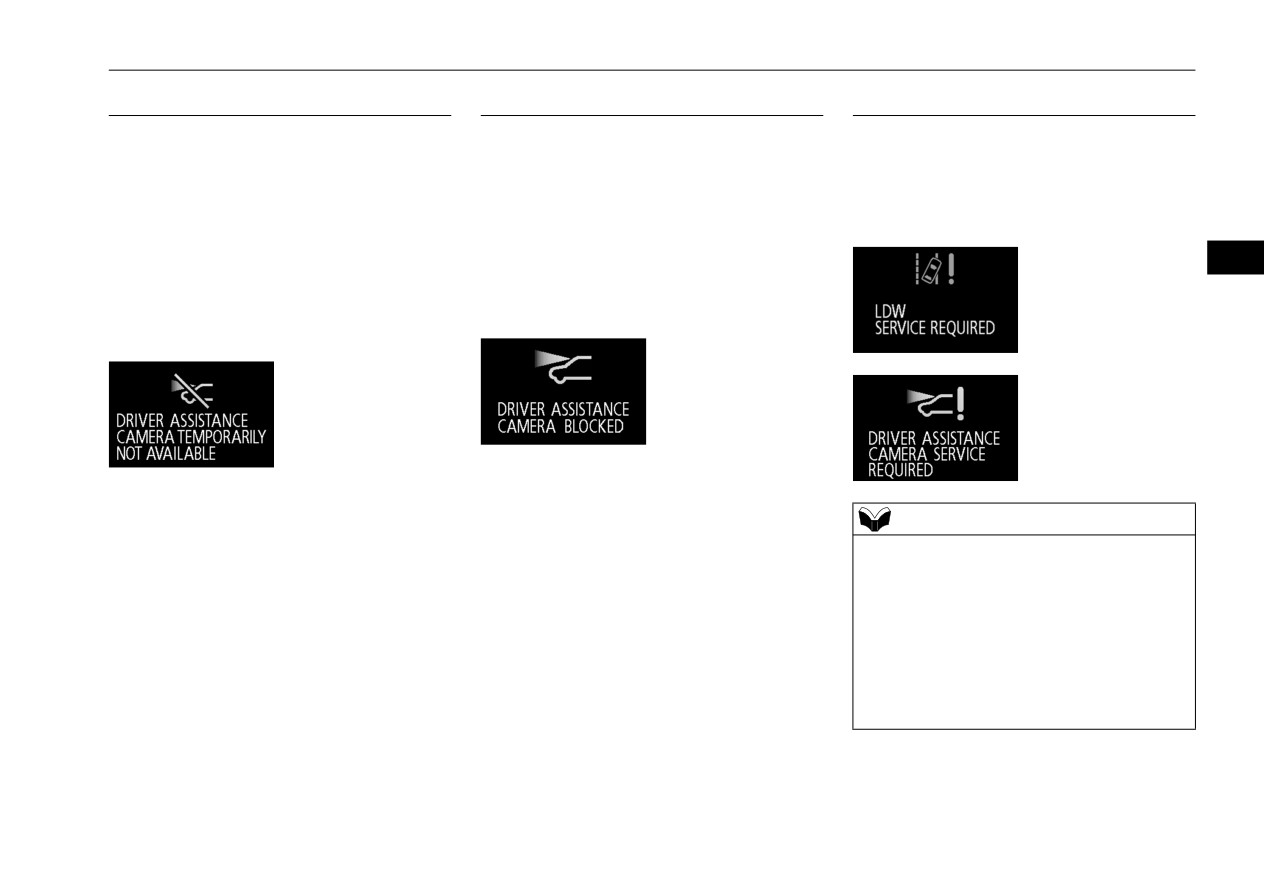
/': GHDFWLYDWLRQ GXH WR IDXOW
The alarm shown below is displayed if the
The alarm shown below is displayed if the
If the LDW is deactivated due to a malfunc-
system becomes temporarily unavailable due
system becomes temporarily unavailable due
tion in the system, the either alarm shown
to the high or low temperature of the sensor.
to the dirty windshield of the sensor.
below is displayed. Contact a certified Mit-
After temperature of the sensor has been in
After having cleaned the windshield, the sys-
subishi EV dealer for inspection of the sys-
range, the system will automatically return to
tem will automatically return to operation.
tem.
operation.
If the alarm continues showing, there is a pos-
5
If the alarm continues showing, there is a pos-
sibility that the LDW has a malfunction. Con-
sibility that the LDW has a malfunction. Con-
tact a certified Mitsubishi EV dealer for
tact a certified Mitsubishi EV dealer for
inspection of the sensor.
inspection of the system.
NOTE
z If the sensor or its surrounding area becomes
extremely high temperature when parking
the vehicle under a blazing sun, the “LDW
SERVICE REQUIRED” message may
appear.
If the message remains even after the tem-
perature of the sensor or its surrounding area
has been in range, please contact a certified
Mitsubishi EV dealer.
Features and controls
5-121

Tire pressure monitoring system (TPMS)
When the operation mode is put in ON, the
7LUH SUHVVXUH PRQLWRULQJ
NOTE
TPMS warning light normally illuminates
• On vehicles with Type 2 sensor which has
V\VWHP 7306
and goes off a few seconds later.
the rubber air valve (D), replace rubber air
N00530201700
valve (D) with new one when the tire is
If one or more of the vehicle tires is signifi-
The tire pressure monitoring system (TPMS)
replaced.
cantly under-inflated, the warning light will
uses tire inflation pressure sensors (A) on the
For details, please contact a certified
remain illuminated while the operation mode
wheels to monitor the tire inflation pressures.
Mitsubishi EV dealer.
is put in ON.
The system only indicates when a tire is sig-
5
Type 1
Refer to “If the warning light / display illumi-
nificantly under-inflated.
nates while driving” on page 5-123 and take
the necessary measures.
NOTE
z In addition, the warning display is displayed
on the information screen in the multi-infor-
mation display.
Type 2
NOTE
z The TPMS is not a substitute for regularly
CAUTION
checking tire inflation pressures.
z If the TPMS warning light does not illumi-
Be sure to check the tire inflation pressures
nate when the operation mode is put in ON,
as described in “Tires” on page 9-12.
it means that the TPMS is not working prop-
7306 ZDUQLQJ OLJKW GLVSOD\
z The tire inflation pressure sensor
(A) is
erly. Have the system inspected by a certified
N00532701392
installed in the illustrated location.
Mitsubishi EV dealer.
• On vehicles with Type 1 sensor which has
In such situations, a malfunctioning of the
the metallic air valve (B), replace grommet
system may be preventing the monitoring of
and washer (C) with the new ones when the
the tire pressure. Avoid sudden braking,
tire is replaced.
sharp turning and high-speed driving.
5-122
Features and controls
Tire pressure monitoring system (TPMS)
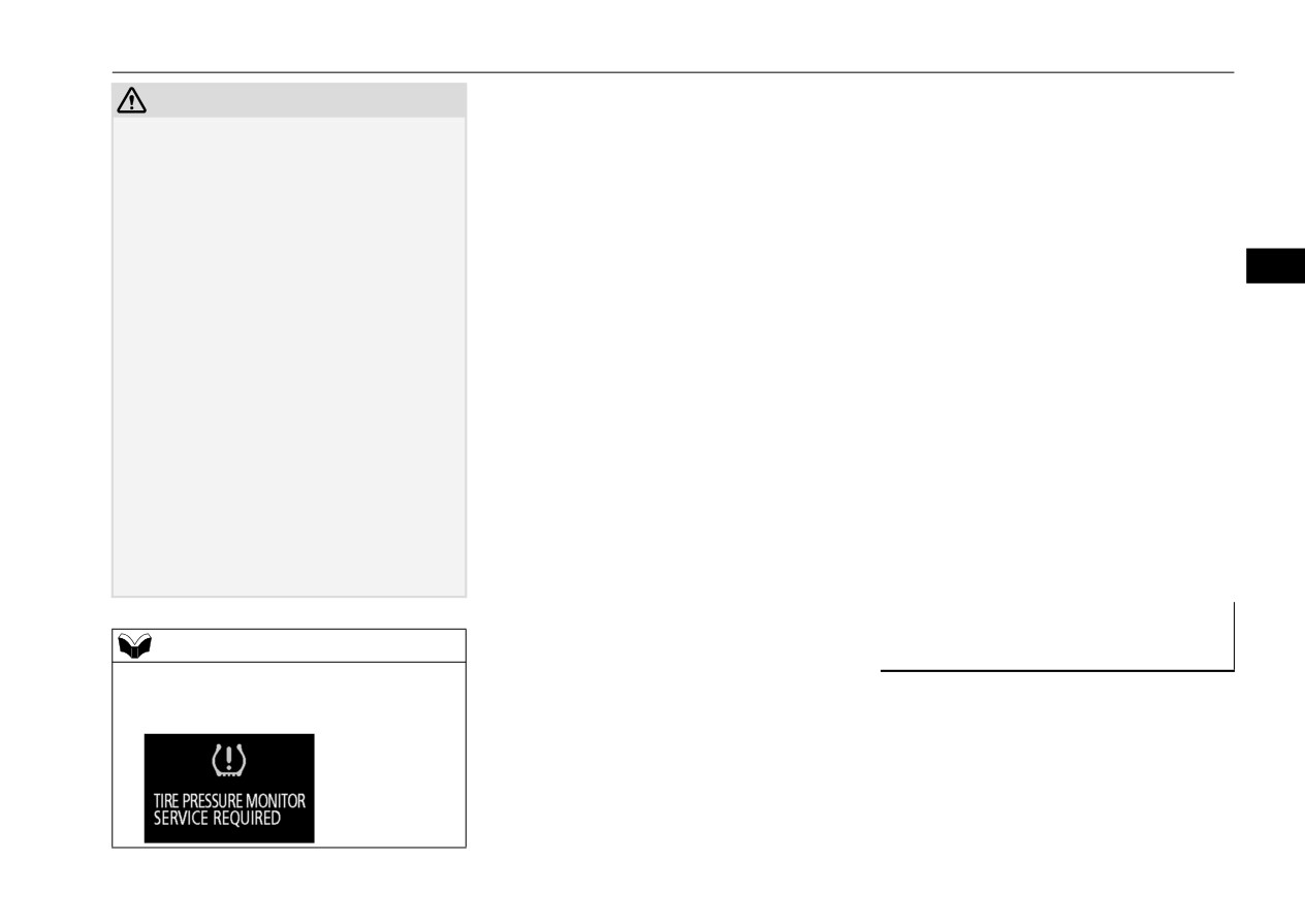
Each tire, should be checked monthly when
TPMS malfunction indicator is combined
CAUTION
cold and inflated to the inflation pressure rec-
with the low tire pressure telltale.
z
If a malfunction is detected in the TPMS, the
ommended by the vehicle manufacturer on
When the system detects a malfunction, the
TPMS warning light will blink for approxi-
the vehicle placard or tire inflation pressure
telltale will flash for approximately one min-
mately 1 minute and then remain continu-
label. (If your vehicle has tires of a different
ute and then remain continuously illuminated.
ously illuminated. The warning light will
size than the size indicated on the vehicle
This sequence will continue upon subsequent
issue further warnings each time the Plug-in
Hybrid EV system is restarted as long as the
placard or tire inflation pressure label, you
vehicle start-ups as long as the malfunction
malfunction exists.
should determine the proper tire inflation
exists.
5
Check to see whether the warning light goes
pressure for those tires.)
When the malfunction indicator is illumi-
off after few minutes driving.
As an added safety feature, your vehicle has
nated, the system may not be able to detect or
If it then goes off during driving, there is no
been equipped with a TPMS that illuminates
signal low tire pressure as intended.
problem.
a low tire pressure telltale when one or more
TPMS malfunctions may occur for a variety
However, if the warning light does not go
of your tires is significantly under-inflated.
of reasons, including the installation of
off, or if it blinks again when the Plug-in
Accordingly, when the low tire pressure tell-
replacement or alternate tires or wheels on the
Hybrid EV system is restarted, have the
tale illuminates, you should stop and check
vehicle that prevent the TPMS from function-
vehicle inspected by a certified Mitsubishi
your tires as soon as possible, and inflate
ing properly. Always check the TPMS mal-
EV dealer.
In such situations, a malfunctioning of the
them to the proper pressure. Driving on a sig-
function telltale after replacing one or more
system may be preventing the monitoring of
nificantly under-inflated tire causes the tire to
tires or wheels on your vehicle to ensure that
the tire pressure. For safety reasons, when
overheat and can lead to tire failure.
the replacement or alternate tires and wheels
the warning light appears while driving,
Under-inflation also reduces fuel efficiency
allow the TPMS to continue to function prop-
avoid sudden braking, sharp turning and
and tire tread life, and may affect the vehi-
erly.
high-speed driving.
cle’s handling and stopping ability. Please
note that the TPMS is not a substitute for
,I WKH ZDUQLQJ OLJKW GLVSOD\
proper tire maintenance, and it is the driver’s
NOTE
LOOXPLQDWHV ZKLOH GULYLQJ
responsibility to maintain correct tire pres-
z
In addition, the warning display is displayed
N00532801582
sure, even if under-inflation has not reached
on the information screen in the multi-infor-
1. If the TPMS warning light illuminates,
the level to trigger illumination of the TPMS
mation display.
avoiding hard braking, sharp steering
low tire pressure telltale.
maneuvers and high speeds. You should
Your vehicle has also been equipped with a
stop and adjust the tires to the proper
TPMS malfunction indicator to indicate when
inflation pressure as soon as possible.
the system is not operating properly. The
Refer to “Tires” on page 9-12.
Features and controls
5-123

Tire pressure monitoring system (TPMS)
The TPMS may not work normally in the fol-
NOTE
WARNING
lowing circumstances:
z
In addition, the warning display is displayed
z
,I WKH ZDUQLQJ OLJKW GLVSOD\ LOOXPLQDWHV
on the information screen in the multi-infor-
ZKLOH \RX DUH GULYLQJ DYRLG KDUG EUDNLQJ
z
A wireless facility or device using the
mation display.
VKDUS VWHHULQJ PDQHXYHUV DQG KLJK
same frequency is near the vehicle.
z
When inspecting or adjusting the tire pres-
VSHHGV
z
Snow or ice is stuck inside the fenders
sure, do not apply excessive force to the
'ULYLQJ ZLWK DQ XQGHU LQIODWHG WLUH
and/or on the wheels.
valve stem to avoid breakage.
DGYHUVHO\ DIIHFWV YHKLFOH SHUIRUPDQFH DQG
z
The tire inflation pressure sensor’s battery
z
After inspecting or adjusting the tire pres-
FDQ UHVXOW LQ DQ DFFLGHQW
5
is dead.
sure, always reinstall the valve cap on the
z
Wheels other than Mitsubishi Motors
valve stem.
Without the valve cap, dirt or moisture could
CAUTION
Genuine wheels are being used.
get into the valve, resulting in damage to the
z
Wheels that are not fitted with tire infla-
z
The warning light / display may not illumi-
tire inflation pressure sensor.
tion pressure sensors are being used.
nate immediately in the event of a tire blow-
z
Do not use metal valve caps, which may
out or rapid leak.
z
Wheels whose ID codes are not memo-
cause a metal reaction, resulting in corrosion
rized by the vehicle are used.
and damage of the tire inflation pressure sen-
z
A window tint that affects the radio wave
sors.
NOTE
signals is installed.
z
Once adjustments have been made, the warn-
z
To avoid the risk of damage to the tire infla-
ing light will go off after a few minutes of
tion pressure sensors, have any punctured
driving.
NOTE
tire repaired by a certified Mitsubishi EV
z
Tire inflation pressures vary with the ambi-
dealer. If the tire repair is not done by a certi-
ent temperature. If the vehicle is subjected to
2. If the TPMS warning light remains illumi-
fied Mitsubishi EV dealer, it is not covered
large variations in ambient temperature, the
nated after you have been driving for
by your warranty.
tire inflation pressures may be under-inflated
approximately 20 minutes after you adjust
z
Do not use an aerosol puncture-repair spray
(causing the warning light / display come on)
the tire inflation pressure, one or more of
on any tire.
when the ambient temperature is relatively
Such a spray could damage the tire inflation
the tires may have a puncture. Inspect the
low. If the warning light / display comes on,
pressure sensors.
tire and if it has a puncture, have it
adjust the tire inflation pressure.
z
Using the tire repair kit may damage the tire
repaired by a certified Mitsubishi EV
inflation pressure sensor. The vehicle must
dealer as soon as possible.
promptly be inspected and repaired by a cer-
tified Mitsubishi EV dealer after using the
tire repair kit.
5-124
Features and controls
Tire pressure monitoring system (TPMS)
Refer to
“Multi-information display
:KHQHYHU WKH WLUHV DQG ZKHHOV
*HQHUDO LQIRUPDWLRQ
switch” on page 5-142.
DUH UHSODFHG ZLWK QHZ RQHV
N00533001291
Refer to “Changing the function settings”
N00532901219
on page 5-153.
Your TPMS operates on a radio frequency
If new wheels with new tire inflation pressure
2. Lightly press the multi-information dis-
subject to Federal Communications Commis-
sion
(FCC) Rules
(For vehicles sold in
sensors are installed, their ID codes must be
play switch to select “
” (tire
U.S.A.) and Industry Canada Rules (For vehi-
programmed into the TPMS. Have tire and
ID set change).
cles sold in Canada). This device complies
wheel replacement performed by a certified
3. Hold down the multi-information display
with part 15 of FCC Rules and Industry Can-
5
Mitsubishi EV dealer to avoid the risk of
switch for approximately
3 seconds or
ada licence-exempt RSS standard(s).
damaging the tire inflation pressure sensors.
more. The setting changes to the selected
Operation is subject to the following two con-
If the wheel replacement is not done by a cer-
tire ID set.
ditions.
tified Mitsubishi EV dealer, it is not covered
by your warranty.
z This device may not cause harmful inter-
ference.
CAUTION
z This device must accept any interference
z The use of non-genuine wheels will prevent
received, including interference that may
the proper fit of the tire inflation pressure
cause undesired operation.
sensors, resulting air leakage or damage of
the sensors.
CAUTION
z Changes or modifications not expressly
approved by the manufacturer for compli-
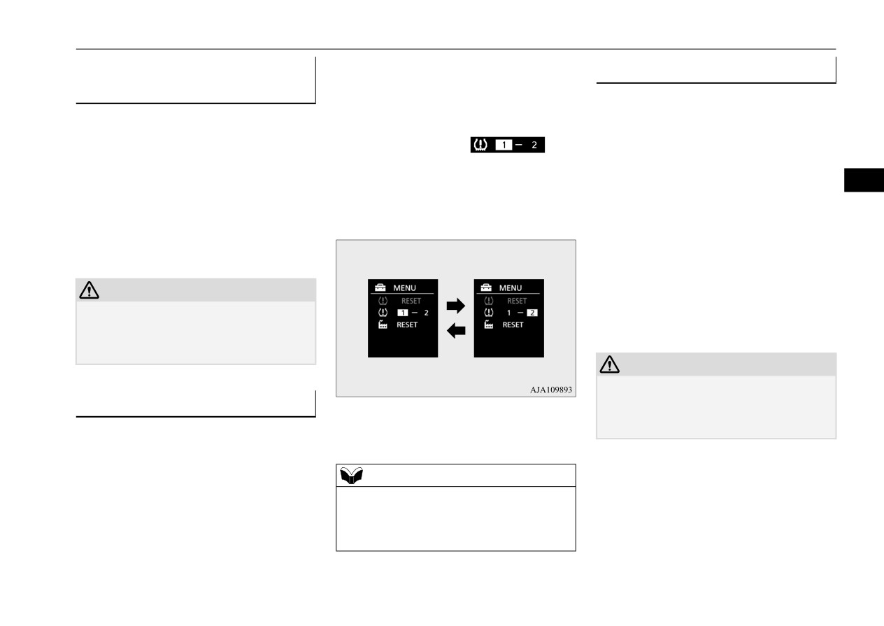
7LUH ,' VHW FKDQJH
4. The valid tire ID set is changed, and the
ance could void the user’s authority to oper-
N00584300055
number of the TPMS SET indicator is
ate the equipment.
In case that 2 sets of tire inflation pressure
changed.
sensor ID are registered in the receiver, the
valid tire ID set can be changed by following
NOTE
procedure.
z Each time this procedure is done, the tire ID
set is changed. (1 - 2 - 1 - 2 …)
1. Operate the multi-information display
z The tire ID set is NOT changed, in case that
switch to switch the information screen to
only 1 set of ID is registered.
the menu screen.
Features and controls
5-125
Rear-view camera (if so equipped)
WARNING
CAUTION
z
1HYHU UHO\ VROHO\ RQ WKH UHDU YLHZ FDPHUD
z If the camera lens gets dirty, a clear image
WR FOHDU WKH DUHD EHKLQG
\RXU YHKLFOH
cannot be obtained. As necessary, rinse the
$OZD\V FKHFN YLVXDOO\ EHKLQG DQG DOO
lens with clean water and gently wipe with a
DURXQG \RXU YHKLFOH IRU SHUVRQV DQLPDOV
clean, soft cloth.
REVWUXFWLRQV RU RWKHU YHKLFOHV
)DLOXUH WR
z To avoid damaging the camera;
GR VR FDQ UHVXOW LQ YHKLFOH GDPDJH VHULRXV
• Do not rub the cover excessively or polish
LQMXU\ RU GHDWK
it by using an abrasive compound.
5
z
7KH UHDU YLHZ FDPHUD LV DQ DLG V\VWHP IRU
• Do not disassemble the camera.
EDFNLQJ XS EXW LW LV QRW D VXEVWLWXWH IRU
• Do not splash hot water directly on the lens.
\RXU YLVXDO FRQILUPDWLRQ
• Do not spray the camera and its surround-
z
7KH YLHZ RQ WKH VFUHHQ LV OLPLWHG DQG
ings with high-pressure water.
REMHFWV RXWVLGH WKH YLHZ VXFK DV XQGHU WKH
• Make sure that the liftgate is securely
EXPSHU RU DURXQG HLWKHU FRUQHU RI WKH
5HDU YLHZ FDPHUD LI VR
closed when backing up.
EXPSHU HQG FDQQRW EH VHHQ RQ WKH VFUHHQ
HTXLSSHG
N00546201415
5HIHUHQFH OLQHV RQ WKH VFUHHQ
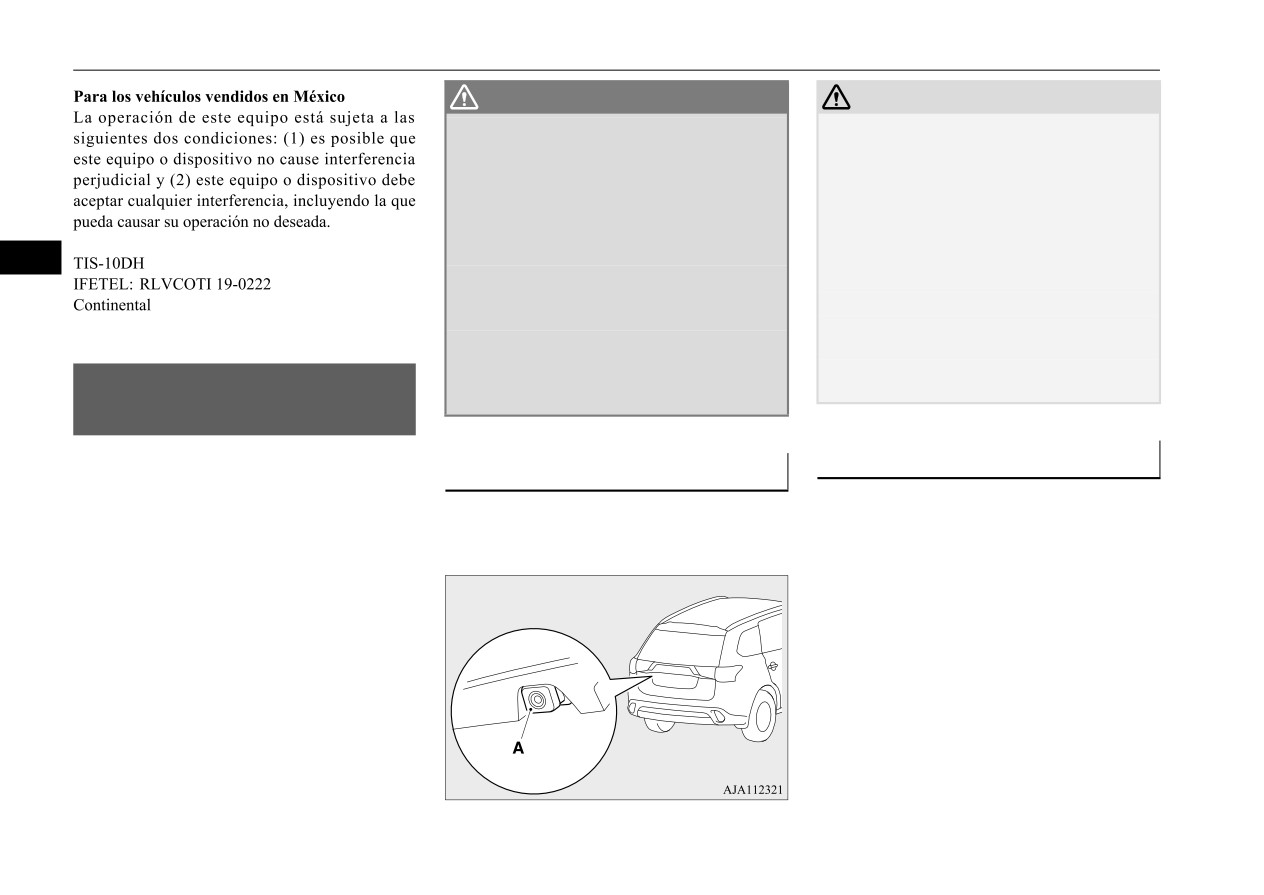
/RFDWLRQ RI UHDU YLHZ FDPHUD
When the select position
is in
the
“R”
(REVERSE) position with the operation
The rear-view camera (A) is in the liftgate, at
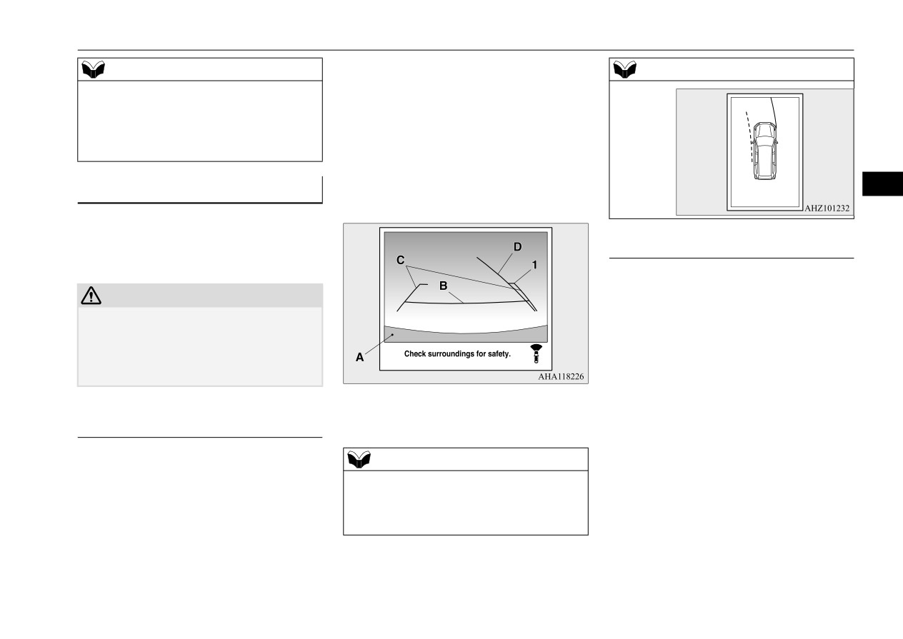
Reference lines and upper surface of the rear
mode of the power switch in ON, the rear-
the left side of the liftgate handle.
bumper (A) are displayed on the screen.
view image will be displayed on the screen of
the Smartphone-link Display Audio (SDA).
z Red line (B) indicates approximately 20
When the select position is shifted out of the
inches (50 cm) behind the rear bumper.
“R”
(REVERSE) position, the rear-view
z Two Green lines (C) indicate approxi-
image will go off.
mately 8 inches (20 cm) outside of the
vehicle body.
z Short transverse lines (1 to 3) indicate dis-
tance from the rear bumper.
5-126
Features and controls

Rear-view camera (if so equipped)
CAUTION
CAUTION
In the following cases, objects shown on the
• When there is a downward slope behind the
screen will appear to be farther off than they
vehicle, objects shown on the screen will
actually are.
appear to be closer than they actually are.
• When the rear of the vehicle is weighed
down with the weight of passengers and
luggage in the vehicle.
5
1: Approximately at the rear edge of the
rear bumper (if so equipped)
2: Approximately 39 inches (100 cm)
3: Approximately 79 inches (200 cm)
A: Actual objects
B: Objects shown on the screen
CAUTION
A: Actual objects
B: Objects shown on the screen
z
The rear-view camera uses a wide-angle
• When there is an upward slope behind the
lens. As a result, images and distances shown
on the screen are not exact.
vehicle.
z
Never rely solely on the reference lines. The
reference lines indicating distance and vehi-
cle width are based on a level, flat road sur-
face.
Actual distance may be different from dis-
tance indicated by the lines on the screen,
depending on the loading condition of the
vehicle and road surface condition.
Also, your vehicle width indicated by the
reference lines may be different from the
A: Actual objects
actual vehicle width.
B: Objects shown on the screen
For example;
Features and controls
5-127

Multi Around Monitor (if so equipped)
CAUTION
CAUTION
NOTE
• When the vehicle is approaching a truck,
• When there is an object behind the vehicle
• When sun light or headlights shine directly
the reference lines indicate that your vehi-
that has upper sections projecting in the
into the lens.
cle will clear the truck. In reality, the truck
direction of the vehicle, the reference lines
is in your path.
on the screen will indicate that point A is
the farthest point and point B is the closest
0XOWL $URXQG 0RQLWRU LI VR
point to the vehicle. In reality, point A and
HTXLSSHG
B are actually the same distance from the
5
N00587200084
vehicle, and point C is farther off than point
A and B.
The Multi Around Monitor system uses four
cameras,
“Front-view camera”,
“Side-view
cameras
(right and left)” and
“Rear-view
camera”, and displays composite views from
those cameras on a screen in the Smartphone-
link Display Audio (SDA).
The Multi Around Monitor system will assist
the driver to park the vehicle in a narrow or
parallel parking space.
WARNING
NOTE
z %HIRUH XVLQJ WKH 0XOWL $URXQG 0RQLWRU
z Mirror image is displayed on the screen.
V\VWHP UHDG WKLV HQWLUH VHFWLRQ WR IXOO\
z The display language of the screen is possi-
XQGHUVWDQG WKH OLPLWDWLRQV RI WKLV V\VWHP
ble can be changed.
)DLOXUH WR IROORZ LQVWUXFWLRQV FRXOG UHVXOW
For details, please refer to the separated
LQ DQ DFFLGHQW
owner’s manual.
z 7KH 0XOWL $URXQG 0RQLWRU V\VWHP LV DQ
z Under certain circumstances, it may become
DLG V\VWHP WR KHOS REVHUYH DURXQG WKH
difficult to see an image on the screen, even
YHKLFOH
,W LV QRW D VXEVWLWXWH IRU
\RXU
when the system is functioning correctly.
YLVXDO FRQILUPDWLRQ
• In a dark area, such as at night.
z 1HYHU UHO\ VROHO\ RQ WKH
0XOWL $URXQG
• When water drops or condensation are on
0RQLWRU V\VWHP 7KH YLHZ RQ WKH VFUHHQ LV
the lens.
OLPLWHG DQG REMHFWV RXWVLGH WKH YLHZ FDQ
QRW EH VHHQ RQ WKH VFUHHQ
5-128
Features and controls
Multi Around Monitor (if so equipped)
CAUTION
CAUTION
z Before using the Multi Around Monitor,
z To avoid damaging the camera;
make sure that all doors and the liftgate are
• Do not rub the cover excessively or polish
closed and the outside mirrors are unfolded.
it by using an abrasive compound.
If an outside mirror is folded and/or if a front
• Do not disassemble the camera.
door and/or the liftgate is open, the areas dis-
• Do not splash hot water directly on the lens.
played on the Multi Around Monitor will not
• Do not spray the camera and its surround-
be appropriate.
ings with high-pressure water.
5
• Make sure that the liftgate is securely
closed when backing up.
/RFDWLRQ RI HDFK FDPHUD
z Do not attach anything on the camera and/or
surrounding areas. Doing so will disturb the
camera.
A- Rear-view camera
B- Front-view camera
C- Side-view camera
CAUTION
z If the camera lens gets dirty, a clear image
cannot be obtained. As necessary, rinse the
lens with clean water and gently wipe with a
clean, soft cloth.
Features and controls
5-129

Multi Around Monitor (if so equipped)
5DQJH RI YLHZ RI WKH 0XOWL $URXQG 0RQLWRU
N00587300027
The range of view of the Multi Around Monitor cameras is limited to the area shown in the illustrations. It cannot show around the both sides and
the lower part of the front and rear bumpers, etc. While driving, be sure to visually confirm safety around the vehicle.
5DQJH RI YLHZ RI WKH 0XOWL $URXQG 0RQLWRU FDPHUDV
5
A: Front-view camera
B: Side-view camera (Right)
C: Side-view camera (Left)
D: Rear-view camera
5-130
Features and controls

Multi Around Monitor (if so equipped)
7\SHV RI YLHZV RI WKH 0XOWL
6LGH YLHZ 5HDU YLHZ PRGH
6LGH YLHZ )URQW YLHZ PRGH
$URXQG 0RQLWRU
Views of the passenger’s side of the vehicle
Views of the passenger’s side of the vehicle
N00587400073
and behind the vehicle are displayed.
and the front of the vehicle are displayed.
Two different types of views are displayed on
the left side and the right side respectively.
5
%LUG¶V H\H YLHZ 5HDU YLHZ PRGH
Views of the surroundings of the vehicle and
behind the vehicle are displayed.
CAUTION
%LUG¶V H\H YLHZ )URQW YLHZ PRGH
z The camera uses a special lens. As a result,
Views of the surroundings of the vehicle and
images and distances shown on the screen
are not exact.
the front of the vehicle are displayed.
NOTE
z Because the cameras have a special lens, the
lines on the ground between parking spaces
may not look parallel on the screen.
z Under certain circumstances, it may become
difficult to see an image on the screen, even
when the system is functioning correctly.
• In a dark area, such as at night.
Features and controls
5-131

Multi Around Monitor (if so equipped)
NOTE
NOTE
6ZLWFKLQJ RI WKH VFUHHQ
6HOHFW
• When water drops or condensation are on
z The passenger’s side screen can be switched
SRVLWLRQ LV ³5´
5(9
(56(
the lens.
to the side-view by pressing the camera
• When sun light or headlights shine directly
switch.
If the camera switch is pressed, the mode of
into the lens.
Multi Around Monitor is switched, Bird’s
• When a fluorescent light shines directly
eye-view/Rear-view
mode
Side-
into the lens.
2SHUDWLRQ ZLWK WKH VZLWFK
view/Rear-view mode
z
If the atmospheric temperature is extremely
5
hot or extremely cold, the camera images
When the camera switch (A) is pressed, the
may not be clear.
bird’s eye-view/front-view is displayed.
6ZLWFKLQJ RI WKH VFUHHQ
6HOHFW
There is no abnormality.
SRVLWLRQ LV RWKHU WKDQ ³5´
z
If a wireless device is installed near the cam-
5(9
(56(
era, the camera images may cause electrical
system interference and the system may stop
functioning properly.
If the camera switch is pressed, the mode of
Multi Around Monitor is switched, Bird’s
eye-view/Front-view mode
Side-
+RZ WR XVH WKH 0XOWL $URXQG
view/Front-view mode OFF
0RQLWRU
N00587500087
NOTE
The Multi Around Monitor can only be used
z When you place the select position is the “R”
when the operation mode of the power switch
(REVERSE) position with the front-view
is put in ON.
mode displayed on the driver’s side screen,
NOTE
the driver’s side screen switches to the rear-
z
If there is no operation for 3 minutes after
view mode. When you shift the select posi-
2SHUDWLRQ ZLWK WKH VHOHFWRU OHYHU
the Multi Around Monitor is displayed by
tion to any other position, the driver’s side
pressing the switch with the select position
screen switches to the front-view mode.
When you place the select position is the “R”
in other than “R” (REVERSE), the display
z When the camera switch is pressed at the
(REVERSE) position, the bird’s eye-
disappears.
vehicle speed of approximately 6 mph (10
view/rear-view is displayed on the screen of
km/h) or higher, only the side-view can be
the SDA. When you move the selector lever
displayed on the passenger’s side screen.
to any other position, the display disappears.
5-132
Features and controls
Multi Around Monitor (if so equipped)
z
The Two Green lines (C) indicate the
NOTE
NOTE
approximate vehicle width.
z The front-view will not be displayed when
z
The Orange lines
(D) indicates an
the vehicle speed exceeds approximately 6
expected course when the vehicle moves
mph (10 km/h).
forward with the steering wheel turned. It
z The display of the view may be delayed dur-
disappears when the steering wheel is in
ing switching of the screen.
the neutral position.
z
The approximate distance from the vehi-
+RZ WR UHDG WKH VFUHHQ
5
cle body is as follows:
N00587600062
In any mode other than the Bird’s eye-view
mode, the lines in the screen give the follow-
5HDU YLHZ PRGH
ing information. Use them only as a guide.
N00587700047
Reference lines for the distance and the vehi-
CAUTION
cle width and upper surface of the rear bum-
z If the camera and/or its surrounding area
per (A) are displayed on the screen.
have experienced an impact, the Multi
Around Monitor system may not function
z The Red line (B) indicates approximately
correctly. Have the vehicle inspected by a
20 inches (50 cm) behind the rear edge of
certified Mitsubishi EV dealer.
the rear bumper.
z The Two Green lines (C) indicate the
1-
Approximately 39 inches (100 cm) from
approximate vehicle width.
the front edge of the front bumper
)URQW YLHZ PRGH
z The Orange line (D) indicates an expected
course when the vehicle is reserved with
Reference lines for the distance and the vehi-
NOTE
the steering wheel turned. It disappears
cle width and upper surface of the front bum-
z
When the expected course lines are dis-
when the steering wheel is in the neutral
position.
per (A) are displayed on the screen.
played in the front-view, the expected course
lines are also displayed in the bird’s eye-
z The approximate distance from the vehi-
z The Red line (B) indicates approximately
view (Front: solid line, Rear: broken line).
cle body is as follows:
20 inches (50 cm) from the front edge of
the front bumper.
Features and controls
5-133

Multi Around Monitor (if so equipped)
CAUTION
CAUTION
In the following cases, objects shown on the
• When there is a downward slope behind the
screen will appear to be farther off than they
vehicle, objects shown on the screen will
actually are.
appear to be closer than they actually are.
• When the rear of the vehicle is weighed
down with the weight of passengers and
luggage in the vehicle.
5
1- Approximately
39 inches
(100 cm)
from the rear edge of the rear bumper
2- Approximately
79 inches
(200 cm)
from the rear edge of the rear bumper
A: Actual objects
B: Objects shown on the screen
CAUTION
A: Actual objects
B: Objects shown on the screen
z
The rear-view camera uses a wide-angle
• When there is an upward slope behind the
lens. As a result, images and distances shown
on the screen are not exact.
vehicle.
z
Never rely solely on the reference lines. The
reference lines indicating distance and vehi-
cle width are based on a level, flat road sur-
face.
Actual distance may be different from dis-
tance indicated by the lines on the screen,
depending on the loading condition of the
vehicle and road surface condition.
Also, your vehicle width indicated by the
reference lines may be different from the
A: Actual objects
actual vehicle width.
B: Objects shown on the screen
For example;
5-134
Features and controls

Multi Around Monitor (if so equipped)
CAUTION
CAUTION
NOTE
• When the vehicle is approaching a truck,
• When there is an object behind the vehicle
z When the expected course lines are dis-
the reference lines indicate that your vehi-
that has upper sections projecting in the
played in the rear-view, the expected course
cle will clear the truck. In reality, the truck
direction of the vehicle, the reference lines
lines are also displayed in the bird’s eye-
is in your path.
on the screen will indicate that point A is
view (Front: broken line, Rear: solid line).
the farthest point and point B is the closest
point to the vehicle. In reality, point A and
B are actually the same distance from the
5
vehicle, and point C is farther off than point
A and B.
Features and controls
5-135