Mitsubishi Outlander (2022 year). Manual in english - page 8

Type-A port: 5 volt, 12W, 2.4A
. Do not use a reversible USB cable. Using
The external device will be charged continu-
the reversible USB cable may damage the
ously while the ignition switch is in the ACC or
connector.
ON position.
Do not charge many devices at the same time by
WIRELESS CHARGER (if so
using a multi-plug adapter.
equipped)
Do not allow water or any liquid to contact the
The wireless charger is located on the lower
outlet. If liquid splashed on the charging port or
part of the instrument panel. Lay the smart-
the charging port is clogged, it is recommended
phone on the pad of the wireless charger.
to contact an authorized Mitsubishi Motors
Charging will start automatically. The smart-
dealer.
phone will be charged continuously while the
Some mobile devices cannot be charged
ignition switch is in the ON position.
depending on their specifications.
WAC0301X
Type-C port
WARNING
CAUTION
Type-A port
Never put metallic materials between the
USB (Universal Serial Bus)
Using charging connectors without engine
wireless charger and a smartphone.
CHARGING OUTLET (if so
running may cause the vehicle battery
Those who use a pacemaker or other
discharge.
medical equipment should contact the
equipped)
Before using the USB charging outlet, be
electric medical equipment manufacturer
The USB charging outlet is located on the back
sure the charging port is not clogged. If the
for the possible influences before use.
of the center console box.
charging port is clogged, it can be a cause
Never put cloth over the smartphone
of short-circuit and the connected device
The USB charging outlet can be used only for
during charging process.
and the charging port might be damaged.
charging an external device.
Never charge a smartphone when it is wet.
Do not force a USB device into the
Connect a USB device into the connector.
connector. Inserting the USB device tilted
Never put metallic materials or small
Charging will start automatically.
or up-side-down into the connector may
goods such as a cigarette lighter.
The maximum output of each port is:
damage the connector. Make sure that the
Never put F.A.S.T.-key near the wireless
Type-C port: 5 volt, 15W, 3A
USB device is connected correctly into the
charger.
connector.
2-64
Instruments and controls

NOTE:
Only a Qi compatible smartphone can be
CAUTION
used.
The smartphone may be warmed during
. Do not put an RFID/NFC card between the
wireless charger and a smartphone. This
charging process and the charging may
could cause data corruption in the card.
stop by the protection function of the
wireless charger. This is not a malfunc-
. Do not use the wireless charger with dust
tion. If this occurs, restart charging after
accumulated or dirt on the pad.
the smartphone cooled down.
. Do not hit the surface of the wireless
The wireless charging process may be
charger.
stopped by the status of the smartphone
(battery temperature, etc.).
Wireless charger Indicator
If a radio noise interference occurs
The indicator will illuminate in orange when the
during charging process, put the smart-
WAC0370X
charging process is started.
phone’s coil position onto the center
("Qi" logo) position of the wireless
When the charging has completed, the indicator
Operation of the wireless charger
illuminates in green.
charger.
To use the wireless charger, it is necessary that
The wireless charging process will stop
If a malfunction occurs or the charging process
the coil in the charging pad aligns with the coil
during process of searching the F.A.S.T.-
has stopped, the indicator will blink in orange.
in your smartphone. The most efficient area for
key.
charging is just on the "Qi" logo
. Place the
The wireless charging process will not be
coil of your smartphone in the charging pad,
started when a USB (Universal Serial
targeting on the "Qi" logo. Because the location
Bus) cable is connected to the smart-
of the coil varies depending on the smartphone,
phone. The indicator may illuminate in
you will need to try and find the area that suits
orange or blink if the smartphone is put
your smartphone.
on the wireless charger with a USB cable
Because some smartphone cases or accessories
connected. However, charging is not
may adversely affect charging, remove them
performed.
before wireless charging.
Depending on the type of the smart-
Turn off the vibration function of the smart-
phone, the indicator may remain illumi-
phone before wireless charging.
nated in orange even when the charging
Instruments and controls
2-65
process has been completed.
ISED Compliance Statement
(2) Cet appareil doit accepter toute inter-
ference recue, y compris les interferences
This device complies with RSS-Gen of IC
FCC ID: BEJWC500MNM
pouvant entrainerun fonctionnement indesir-
Rules
IC: 2703H-WC500MNM
able.
Operation is subject to the following two
This device complies with part 15 of the FCC
Les changements ou modifications non ex-
conditions:
Rules and RSS-Gen of IC Rules.
pressement approuves par LG Vehicle Com-
(1) This device may not cause harmful
Operation is subject to the following two
ponents Company pourraient annuler
interference, and
conditions:
l’autorite de l’utilisateura utilizer l’equipe-
(2) This device must accept any interference
ment.
(1) This device may not cause harmful
received, including interference that may
interference, and
Déclaration d’exposition aux radiations RF
cause undesired operation.
de l’ISED: Cet équipement est conforme aux
(2) This device must accept any interference
Changes or modifications made to this
limites d’exposition aux rayonnements RF de
received, including interference that may
device, not expressly approved by LG Vehicle
l’ISED définies pour un environnement non
cause undesired operation.
Components Company, will void the user’s
contrôlé. Cet appareil et son antenne ne
Changes or modifications not expressly
authority to operate the equipment.
doivent pas être situés ou fonctionner con-
approved by the party responsible for
ISED RF Radiation Exposure Statement:
jointement avec une autre antenne ou un
compliance could void the user’s authority
This equipment complies with ISED RF
autre émetteur.
to operate the equipment.
Radiation exposure limits set forth for an
Cet équipement doit être installé pour
RF Radiation Exposure Statement: This
uncontrolled environment. This device and
fonctionner avec une distance minimale de
equipment complies with FCC RF Radiation
its antenna must not be co-located or
15cm entre le radiateuret le corps de
exposure limits set forth for an uncontrolled
operating in conjunction with any other
l’utilisateur final.
environment.
antenna or transmitter. This equipment
This device and its antenna must not be co-
should be installed to operate with a mini-
located or operating in conjunction with any
mum distance of 15cm between the radiator
other antenna or transmitter.
and the end-user’s body and arms.
This equipment should be installed and
IDéclaration d’avertissement ISED
operated with a minimum distance of 15cm
Son fonctionnement est soumis aux deux
between the radiator and your body.
conditions suivantes:
(1) Cet appareil ne doit pas provoquerd’in-
terferences nuisibles, et
2-66
Instruments and controls
EMERGENCY CALL SYSTEM
(e-CALL) (if so equipped)
EMERGENCY SUPPORT
MITSUBISHI CONNECT.
Only use this service in case of an
emergency. There may be a penalty for
MITSUBISHI CONNECT provide various ser-
— The MITSUBISHI CONNECT
inappropriate use of the service.
vices to support dealing with emergencies of the
network system is disabled.
Radio waves could adversely affect electric
subscribed vehicle and the driver.
— The vehicle moves outside the
medical equipment. Individuals who use a
For example, in case of an illness or serious
service area where the TCU (Tele-
pacemaker should contact the device man-
injury, you can seek support by pushing the in-
matics Control Unit) is connected
ufacturer regarding any possible effects
vehicle SOS switch and connecting to the
before using the system.
to the system.
MITSUBISHI CONNECT Response Center.
The TCU (Telematics Control Unit) anten-
— The vehicle is outside the area
The MITSUBISHI CONNECT Response Cen-
na is installed inside the upper central part
where the cellular network service
ter can specify the location of the vehicle via
of the instrument panel. An occupant
is receivable.
GPS, and the information will be sent to the
should not get any closer to the antenna
than specified by the pacemaker manufac-
police or other agencies as needed.
— The vehicle is in a location with
turer. The radio waves from the TCU
poor signal reception such as
For information about other MITSUBISHI
antenna may adversely affect the operation
CONNECT emergency support related services,
tunnels, underground parking
of the pacemaker while
using
the
contact the MITSUBISHI CONNECT Custo-
garages, behind buildings or in
MITSUBISHI CONNECT.
mer Support line at 1-888-564-1411 (For U.S.)
mountainous areas.
or 1-888-576-4878 (For Canada), or refer to the
— The line is busy.
MITSUBISHI CONNECT website https://www.
— The TCU (Telematics Control
mitsubishi-motors.com/en/products/connect.
Unit) or other systems of your
vehicle are not working properly.
WARNING
— It may not be possible to make an
emergency call depending on the
. Please note that the Automatic Collision
severity of a collision and/or
Notification service and Emergency Call
emergency.
function cannot be used in the following
conditions:
Park the vehicle in a safe location and set
— Emergency functions and services
the parking brake before operating the
SOS switch.
will not be available without a
paid subscription to
Instruments and controls
2-67

STORAGE
matics Control Unit) is being used by
CUP HOLDERS
other services.
An indicator light on the SOS switch
shows the readiness of the emergency
CAUTION
support system. If the indicator light is
not illuminated, pushing the SOS switch
Avoid abrupt starting and braking when
does not connect your vehicle to the
the cup holder is being used to prevent
Response Specialist.
spilling the drink. If the liquid is hot, it can
scald you or your passenger.
The indicator light blinks while con-
nected to the MITSUBISHI CONNECT
Use only soft cups in the cup holder. Hard
Response Center.
objects can injure you in an accident.
Even when the indicator light is illumi-
nated, connection to the MITSUBISHI
CONNECT Response Center may not be
WAC0570X
possible. If this occurs in an emergency
situation, contact the authorities by other
Making an emergency call
means.
The SOS switch is located near the map light.
To avoid disconnecting the line, keep the
1. Push the cover to expose the SOS switch
engine running during an emergency call,
2. Push the SOS switch to make an emergency
if it is safe to do so.
call.
3. When the line is connected, speak to the
Response Specialist.
If you want to cancel the emergency call, push
and hold the SOS switch for a few seconds.
NOTE:
. After the SOS switch is pushed, it may
take some time until the system initiates
connection, depending on the technical
environment and whether the TCU (Tele-
2-68
Instruments and controls

WAC0302X
WAC0303X
WAC0304X
Center console
Door (front and rear)
Second row seat
Front
LUGGAGE COMPARTMENT
The second row seat cup holders are located in
the second row seat fold-down armrest.
CAUTION
SOFT BOTTLE HOLDERS
. Do not place cargo higher than the seat-
CAUTION
backs. In a sudden stop or collision,
unsecured cargo could cause personal
injury.
. Do not use bottle holder for any other
objects that could be thrown about in the
vehicle and possibly injure people during
sudden braking or an accident.
. Do not use bottle holder for open liquid
containers.
Instruments and controls
2-69
WAC0364X
WAC0305X
WAC0306X
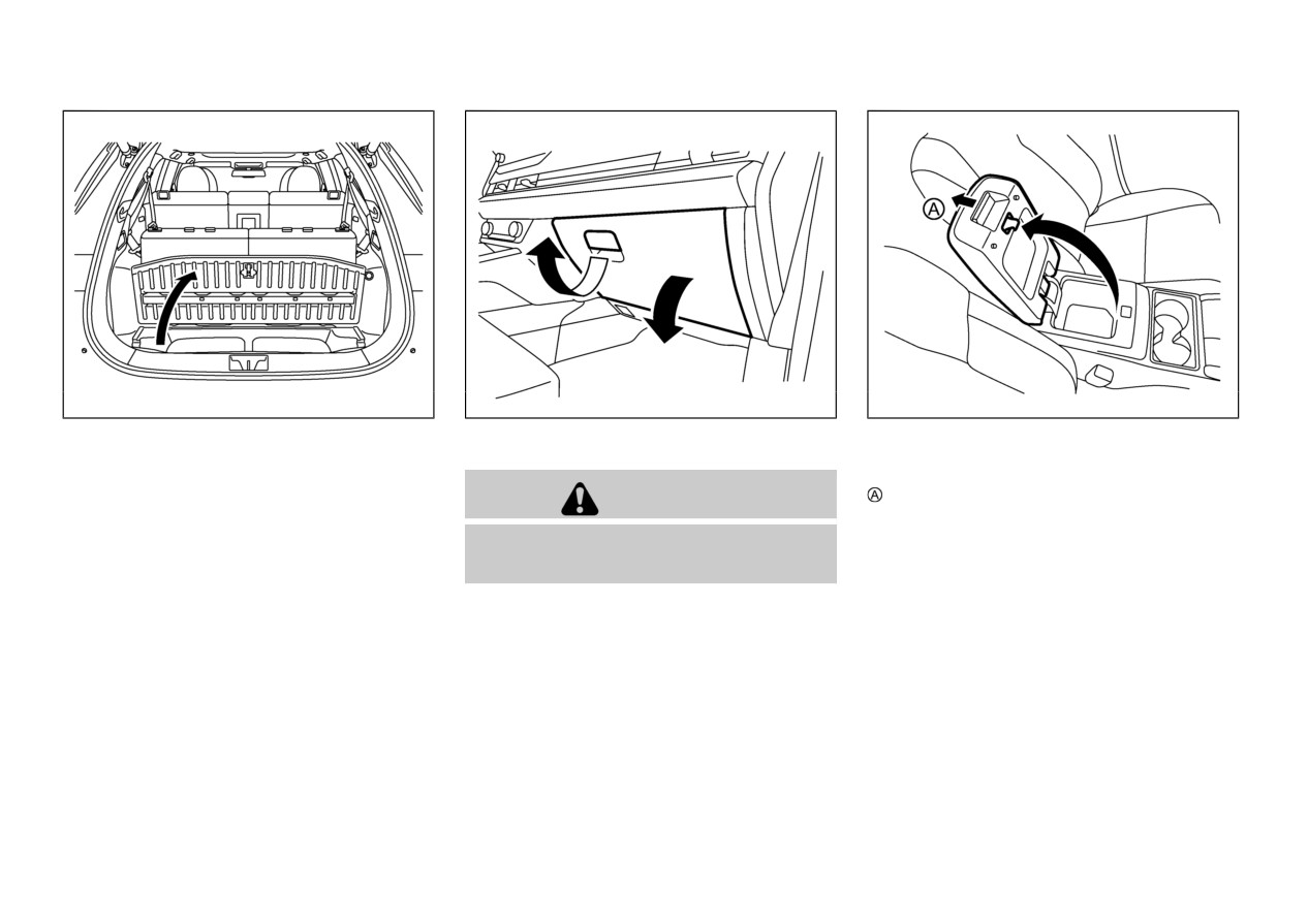
Luggage under space
GLOVE BOX
CONSOLE BOX
To use the luggage under space, pull up the
To open the console box lid, push up the knob
luggage floor board. The luggage under space
WARNING
and pull up the lid.
can be used to storage the head restraints of the
To close, push the lid down until the lock
third row seats. For additional information, refer
Keep glove box lid closed while driving to help
latches.
to “Third row seats” (P.1-9).
prevent injury in an accident or a sudden stop.
To open the glove box, pull the handle.
To close, push the lid in until the lock latches.
The glove box light illuminates when the
headlight switch is turned on.
2-70
Instruments and controls

. Do not leave sunglasses in the sunglasses
holder while parking in direct sunlight.
The heat may damage the sunglasses.
The sunglasses holder is located between the
left and right sunvisors.
To open the sunglasses holder, push and release.
Only store one pair of sunglasses in the holder.
WAC0307X
WAC0486X
SUNGLASSES HOLDER
CARD HOLDER
The card holder is located on the sunvisor.
WARNING
Slide a card in the card holder.
Keep the sunglasses holder closed while driving
to avoid obstructing the driver’s view and to
help prevent an accident.
CAUTION
. Do not use for anything other than
sunglasses.
Instruments and controls
2-71

. Do not apply a total load of more than 6.6
lb (3 kg) for hook
or 44 lb (20 kg) for
hook to a single hook.
WAC0365X
SIC3505
LUGGAGE HOOKS
COAT HOOKS
The luggage hooks
are located as shown.
The coat hooks are located above the rear side
windows.
To use the hooks
, pull it as illustrated. Do not
put heavy load on the hooks when they are in
use to prevent hooks are broken.
WARNING
WARNING
Do not put a hanger or any heavy or pointed
object on the coat hook. If the curtain airbag
was activated, any such item could be pro-
. Always make sure that the cargo is
pelled away with great force and could prevent
properly secured. Use the suitable ropes
the curtain airbag from inflating correctly.
and hooks.
Hang clothes directly on the coat hook (without
. Unsecured cargo can become dangerous in
using a hanger). Make sure there are no heavy
an accident or sudden stop.
or sharp objects in the pockets of clothes that
you hang on the coat hook.
2-72
Instruments and controls
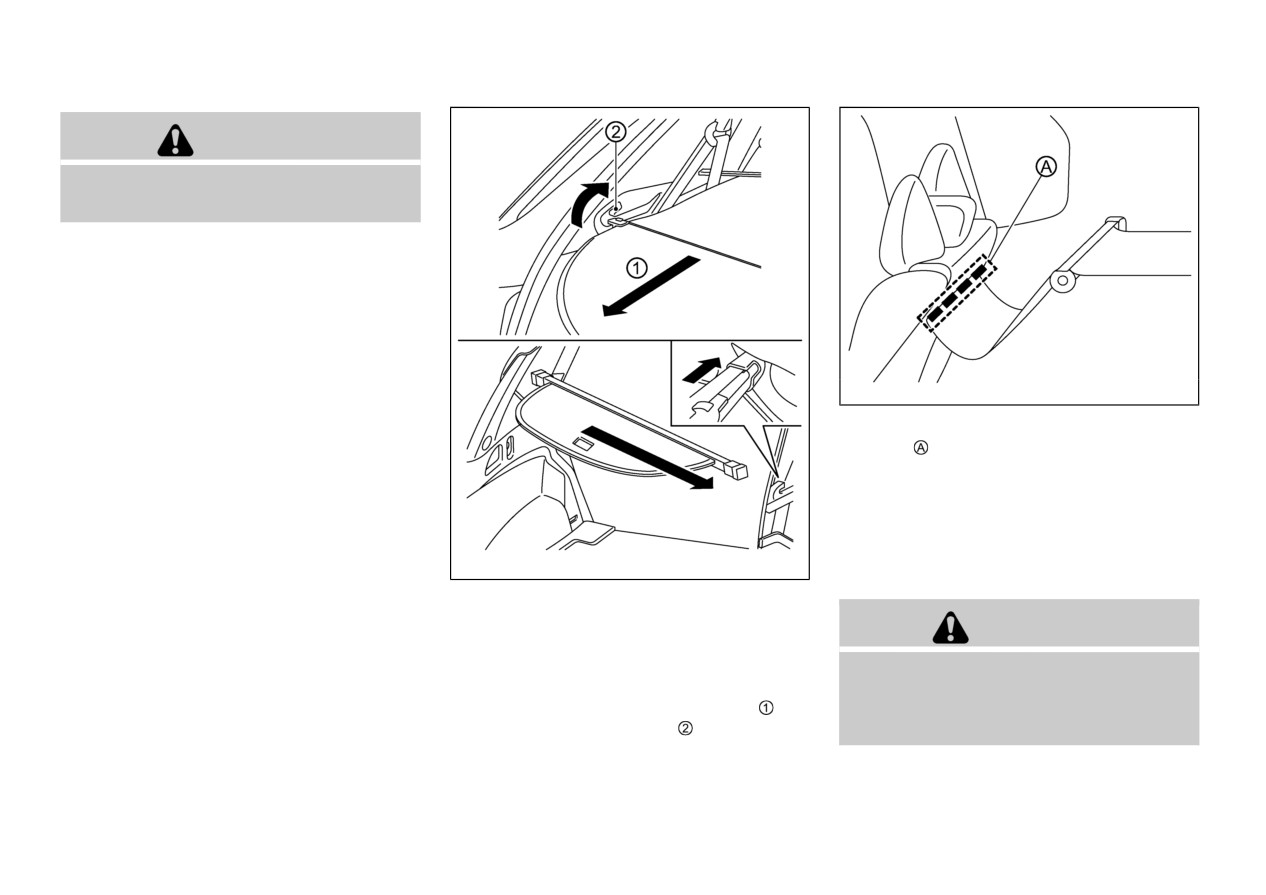
CAUTION
Do not apply a total load of more than 2 lb (1
kg) to the hook.
WAC0631X
To fully cover the luggage area, affix the
fasteners
on the front cover to the back of
the second row seats.
To remove the tonneau cover, stow the cover
and push it at the right end, pull up the right end
of the stored tonneau cover from the holder
located near by the rear pillar, then take it out
WAC0366X
from the cargo area.
TONNEAU COVER (if so
equipped)
WARNING
The tonneau cover keeps the luggage compart-
. Never put anything on the tonneau cover,
ment contents hidden from the outside.
no matter how small. Any object on it
To use the tonneau cover, pull it out
and
could cause an injury in an accident or
insert both sides to the guide
sudden stop.
Instruments and controls
2-73
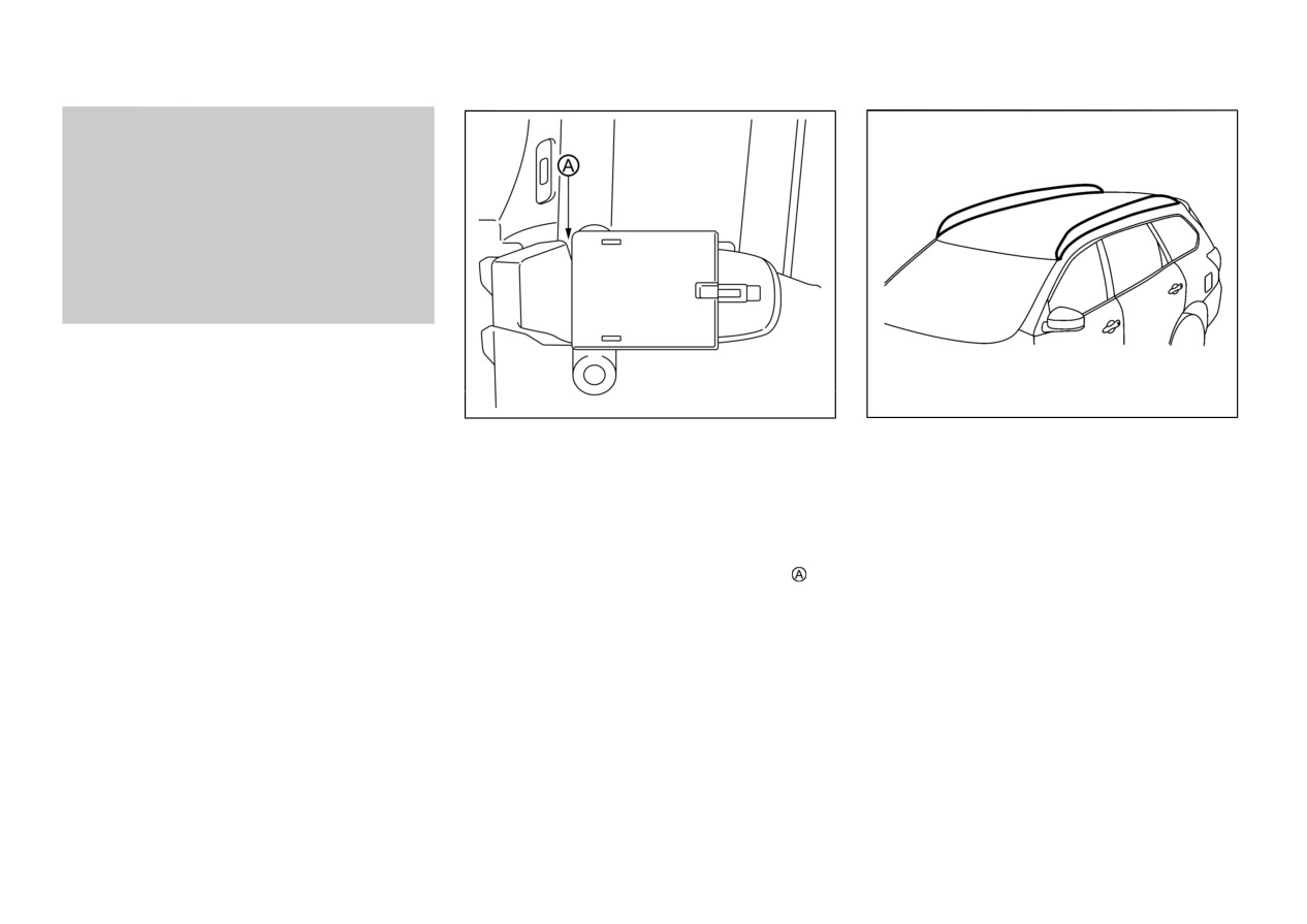
ROOF RAIL (if so equipped)
. Do not leave the tonneau cover in the
vehicle with it disengaged from the holder.
. The child restraint top tether strap may be
damaged by contact with the tonneau
cover or items in the cargo area. Remove
the tonneau cover from the vehicle or
secure it in the cargo area. Also secure any
items in the cargo area. Your child could
be seriously injured or killed in a collision
if the top tether strap is damaged.
WAC0654X
WAC0551X
Do not apply any load directly to the roof side
Storing tonneau cover
rails. Cross bars must be installed before
The tonneau cover can be stored in the luggage
applying load/cargo/luggage to the roof of the
under space when not in use.
vehicle. Mitsubishi Motors genuine accessory
Raise the luggage floor board and store the
cross bars are available through an authorized
tonneau cover.
Mitsubishi Motors dealer. It is recommended
that you visit an authorized Mitsubishi Motors
Insert the front cover in the space
as
dealer for additional information.
illustrated.
The service load capacity for the roof side rails
is 176 lb (80 kg), however do not exceed the
accessory cross bars load capacity.
Be careful that your vehicle does not exceed the
Gross Vehicle Weight Rating (GVWR) or its
Gross Axle Weight Rating (GAWR front and
rear). The GVWR and GAWR are located on
the F.M.V.S.S. or C.V.M.S.S. certification label
2-74
Instruments and controls
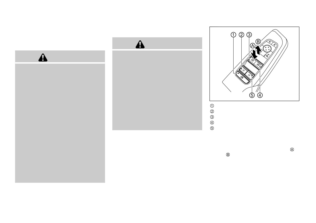
WINDOWS
(located on the driver’s door pillar). For
POWER WINDOWS
additional information regarding GVWR and
GAWR, refer to “Vehicle loading information”
(P.10-15).
WARNING
Make sure that all passengers have their
WARNING
hands, etc. inside the vehicle while it is in
motion and before closing the windows.
Always install the cross bars onto the roof
Use the window lock switch to prevent
side rails before loading cargo of any kind.
unexpected use of the power windows.
Loading cargo directly onto the roof side
To help avoid risk of injury or death
rails or the vehicle’s roof may cause vehicle
through unintended operation of the vehi-
damage.
cle and or its systems, including entrap-
Drive extra carefully when the vehicle is
ment in windows or inadvertent door lock
loaded at or near the cargo carrying
activation, do not leave children, people
WAC0367X
capacity, especially if the significant por-
who require the assistance of others or pets
Window lock button
tion of that load is carried on the cross
unattended in your vehicle. Additionally,
bars.
the temperature inside a closed vehicle on
Rear left passenger side window
a warm day can quickly become high
Driver side window
Heavy loading of the cross bars has the
potential to affect the vehicle stability and
enough to cause a significant risk of injury
Front passenger side window
handling. Drive carefully and avoid sud-
or death to people and pets.
Rear right passenger side window
den or unusual handling maneuvers.
NOTE:
Main power window switch (driver’s
Roof rail cross bars should be evenly
distributed.
If the power window does not close comple-
side)
Do not exceed maximum roof rail cross
tely when driving, slow down the vehicle
To open or close the window, push down or
bars load.
speed and open and close the power window.
pull up
the switch and hold it. The main
Properly secure all cargo with ropes or
The power windows operate when the ignition
switch (driver side switches) will open or close
straps to help prevent it from sliding or
switch is in the ON position, or for about 45
all the windows.
shifting. In a sudden stop or collision,
seconds after the ignition switch is placed in the
unsecured cargo could cause personal
OFF position. If the driver’s or front passen-
injury.
ger’s door is opened during this period of about
45 seconds, power to the windows is canceled.
Instruments and controls
2-75
Locking passengers’ windows
When the lock button is pushed in, only the
driver side window can be opened or closed.
Push it in again to cancel.
WAC0308X
WAC0368X
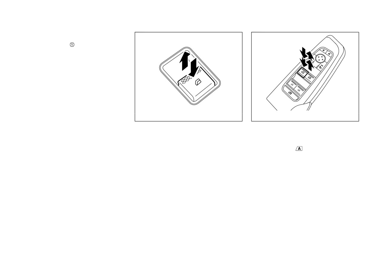
Example
Passenger side power window switch
Automatic operation (if so equipped)
The passenger side switch will open or close
The automatic operation is available for the
only the corresponding window. To open or
switch that has an
mark on its surface.
close the window, push down or pull up the
switch and hold it.
To fully open or close the window, completely
push down or pull up the switch and release it;
the switch need not be held. The window will
automatically open or close all the way. To stop
the window, just push or lift the switch in the
opposite direction.
A light push or pull on the switch will cause the
window to open or close until the switch is
released.
2-76
Instruments and controls
Auto-reverse function (if so
If the windows do not close auto-
procedure above, it is recommended you have
your vehicle checked
by
an
authorized
equipped)
matically
Mitsubishi Motors dealer.
If the power window automatic function (clos-
ing only) does not operate properly, perform the
WARNING
following procedure to initialize the power
window system.
There are some small distances immediately
before the closed position which cannot be
1.
Start the engine.
detected. Make sure that all passengers have
2.
Close the door.
their hands, etc., inside the vehicle before
closing the window.
3.
After starting the engine, open the window
completely by operating the power window
If the control unit detects something caught in
switch.
the window as it is closing, the window will be
4.
Pull the power window switch and hold it to
immediately lowered.
close the window, and then hold the switch
more than 3 seconds after the window is
The auto reverse function can be activated when
the window is closed by automatic operation
closed completely.
when the ignition switch is in the ON position
5.
Release the power window switch. Operate
or for 45 seconds after the ignition switch is
the window by the automatic function to
placed in the OFF position.
confirm the initialization is complete.
Depending on the environment or driving
conditions, the auto reverse function may be
WARNING
activated if an impact or load similar to
something being caught in the window
When the auto-reverse function is canceled, the
occurs.
window will not automatically reverse even if
the control unit detects an obstacle. Make sure
that all passengers have their hands, etc. inside
the vehicle before closing the windows.
If the power window automatic function does
not operate properly after performing the
Instruments and controls
2-77

SUNROOF (if so equipped)
to the CLOSE position
, sunshade will close.
WARNING
Before the sunshade is fully closed, the sunroof
must be completely closed.
In an accident you could be thrown from
To stop the sunshade or sunroof during the
the vehicle through an open sunroof.
operation, push the sunroof switch to either of
Always use seat belts and child restraints.
the OPEN
,
, CLOSE
,
or UP
Do not allow anyone to stand up or extend
position.
any portion of their body out of the
sunroof opening while the vehicle is in
Tilting sunroof
motion or while the sunroof is closing.
To tilt up the sunroof, push the sunroof switch
to the up position
when the sunroof is fully
closed.
CAUTION
To tilt down the sunroof, push the switch to the
WAC0309X
CLOSE position
Remove water drops, snow, ice or sand
from the sunroof before opening.
POWER PANORAMIC SUN-
Comfort mode
Do not place any heavy object on the
ROOF AND SUNSHADE
This is the position used when driving with the
sunroof or surrounding area.
sunroof open. When driving with the sunroof
Sliding sunshade and sunroof
fully open, wind noise may be very loud. Use
The
sunroof and sunshade operate when the
When the sunshade switch is pushed to the
the comfort mode position when driving.
ignition switch is in the ON position, or for
OPEN position
, the sunshade open fully.
Auto-reverse function
about 45 seconds after the ignition switch is
When the sunroof switch is pushed to the OPEN
placed in the OFF position. If the driver’s or
position
, the sunroof opens to the comfort
front passenger’s door is opened during this
mode position. When the switch is pushed
WARNING
period of about
45
seconds, power to the
again, the sunroof opens fully.
sunroof and sunshade is canceled.
Depending on the position of the sunshade, the
There are some small distances just before the
sunshade will open together with the sunroof.
closed position which cannot be detected. Make
sure that all passengers have their hands, etc.
When the sunroof switch is pushed to the
inside the vehicle before closing the sunroof
CLOSE position
, the sunroof will automati-
and sunshade.
cally close. When the sunshade switch is pushed
2-78
Instruments and controls
The auto-reverse function enables the sunroof
3. When the sunroof have stopped in the tilt up
Do not activate the auto-reverse function
and sunshade to automatically reverse when
position and the sunshade have stopped in
intentionally. If hands or face etc. get
something is caught in the sunroof and
the fully closed position, release the switch.
caught in the sunroof, it could cause
sunshade as it is closing. When the control unit
(The resetting procedure is finished.)
serious injury.
detects an obstacle, the sunroof and sunshade
NOTE:
will open immediately.
Do not release the switch until the
Depending on the environment or driving
resetting procedure is finished. If you
CAUTION
conditions, the auto-reverse function may
release the switch, the resetting mode will
activate if an impact or load similar to some-
be cancelled. To perform the resetting
Do not place objects (such as newspapers,
thing being caught in the sunroof and sunshade
procedure again, repeat the procedure
handkerchiefs, etc.) on the sunshade when
occurs.
from step 1.
it is extending or retracting causing
If the auto-reverse function activates consecu-
improper operation or damage to the
sunshade.
tively or the battery is discharged, the sunroof
WARNING
and sunshade may not close properly. In this
Do not push the sunshade arm with your
case, push and hold the switch to the CLOSE
hands, etc., as this may deform it. Im-
The driver is always responsible for operation
position
to close the sunroof.
proper operation or damage to the sun-
of the sunroof including all passenger’s opera-
shade may result.
tion. Failure to follow the warnings and
If the sunroof does not operate
instructions for proper use of the sunroof
Do not put any object into the sunshade
If the sunroof and sunshade do not operate
could result in serious injury or death.
inlet port as this may result in improper
operation or damage the sunshade.
properly, perform the following procedure to
. Do not let children operate the sunroof.
initialize the operation system.
Improper operation by children may cause
Do not hang any object on the arm rail as
an accident. If a child or other person is
this may result in improper operation or
1. Push and hold the switch in direction
caught in the sunroof, it could cause
damage the sunshade.
2. The sunroof will move to the tilt up position
serious injury.
Do not forcefully pull the sunshade. Doing
and the sunshade will move to the fully
. To help avoid risk of injury or death
so may elongate the sunshade. Improper
closed positions in small increments.
through unintended operation of the sun-
operation or damage to the sunshade may
NOTE:
roof, Place the ignition switch in the OFF
result.
If the sunroof and sunshade are both
position, do not leave children and F.A.S.
T.-key inside the vehicle when you leave
open, the sunroof will move to the fully
the vehicle.
closed position, and then the sunshade
will move to the fully closed position.
Instruments and controls
2-79

INTERIOR LIGHTS
CAUTION
. Do not leave the light switch on when the
engine is not running for extended periods
of time to prevent the battery from being
discharged.
. Turn off the lights when you leave the
vehicle.
WAC0552X
WAC0067X
INTERIOR LIGHT SWITCH
MAP LIGHTS
The interior light can be turned ON regardless
Push the button to turn the map lights on. To
of door position. The light will go off after a
turn them off, push the button again.
period of time unless the ignition switch is
placed in the “ON” position when any door is
opened.
The interior lights can be set to operate when
the doors are opened. To turn off the interior
lights when a door is open, push the switch, the
interior lights will not illuminate, regardless of
door position. The lights will go off when the
ignition switch is placed in the “ON” position,
or the driver’s door is closed and locked.
2-80
Instruments and controls

WAC0090X
WAC0310X
WAC0487X
DOME LIGHTS (if so equipped)
REAR PERSONAL LIGHTS (if
VANITY MIRROR LIGHT
The dome lights are located on the ceiling
so equipped)
The vanity mirror light is located on the ceiling
above the second raw seats.
above the vanity mirror.
To turn the rear personal lights on, push the
Push the button to turn the dome lights on. To
button. To turn them off, push the button again.
The vanity mirror light will turn on when the
turn them off, push the button again.
cover on the vanity mirror is opened.
When the cover is closed, the light will turn off.
The lights will also turn off after a period of
time when the lights remain illuminated to
prevent the battery from becoming dis-
charged.
Instruments and controls
2-81

CARGO ROOM LIGHT
The cargo room light illuminate when the
liftgate is opened. When the liftgate is closed,
the lights will turn off.
The light will also turn off after a period of
time when the light remains illuminated after
the ignition switch has been pushed to the
OFF position to prevent the battery from
becoming discharged.
WAC0556X
LIFTGATE LIGHT
To turn the liftgate light on, slide the switch to
. To turn them off, slide the switch to
2-82
Instruments and controls
3 Pre-driving checks and adjustments
Keys
3-2
Liftgate
3-20
Free-hand Advanced Security
Operating manual liftgate
3-21
Transmitter (F.A.S.T.-key)
3-2
Operating power liftgate (if so equipped)
3-22
Doors
3-4
Operating the power liftgate using the hands-free
Locking with key
3-4
access (if so equipped)
3-25
Locking with inside lock knob
3-4
Liftgate close and lock function
3-26
Locking with power door lock switch
3-6
Liftgate release lever
3-27
Automatic door locks
3-6
Height memory function
3-27
Child safety rear door lock
3-6
Fuel filler door
3-28
Free-hand Advanced Security
Opening the fuel filler door
3-28
Transmitter (F.A.S.T.-key)
3-7
How to refuel
3-29
F.A.S.T.-key operating range (models with
Tilt/telescopic steering
3-31
request switch)
3-9
Tilt or telescopic operation
3-32
Door locks/unlocks precaution (models with
Sunvisors
3-32
request switch)
3-9
Pull-up type sunshade (rear door) (if so equipped)
3-33
F.A.S.T.-key operation
3-10
Mirrors
3-33
Battery saver system
3-12
Inside mirror
3-33
Warnings and audible reminders
3-12
Door mirrors
3-34
Troubleshooting guide
3-13
Vanity mirror
3-37
How to use remote keyless entry function
3-15
Driver memory settings (if so equipped)
3-37
Hood
3-19
Memory storage function
3-38
Entry/Exit function
3-39
System operation
3-39

KEYS
1.
F.A.S.T.-key (2 sets)
The key number is stamped on the key number
2.
Emergency key (inside F.A.S.T.-key) (2 sets)
tag as indicated in the illustration. Make a
record of the key number and store the key and
3.
Key number tag
key number tag in separate places, so that you
FREE-HAND ADVANCED SE-
can order a key from
your authorized
CURITY TRANSMITTER (F.A.
Mitsubishi Motors dealer
in
the
event
the
original keys are lost.
S.T.-key)
Your vehicle can only be driven with the Free-
hand Advanced Security Transmitter (F.A.S.T.-
key) which are registered to your vehicle’s F.A.
S.T.-key components and Anti-theft engine
immobilizer components. As many as 4 F.A.S.
T.-keys can be registered and used with one
WAD0161X
vehicle.
Type A
To prevent vehicle theft, take your vehicle and
the remaining F.A.S.T.-keys to an authorized
Mitsubishi Motors dealer to have the ID codes
reprogrammed.
Replacement F.A.S.T.-keys
Only the F.A.S.T.-keys that have been pro-
grammed to the vehicle’s electronics can be
used to start the vehicle.
If you lose the F.A.S.T.-key, you can order a F.
A.S.T.-key from your authorized Mitsubishi
Motors dealer by referring to the key number.
WAD0129X
Type B
3-2
Pre-driving checks and adjustments