Mitsubishi Mirage G4 (2022 year). Manual in english - page 11
Tires
WARNING
WARNING
Tires
z
Never disconnect the battery while the
z
If you are quick-charging your battery,
N00939201693
engine is running, or you could damage
first disconnect the battery cables.
the vehicle’s electrical parts.
z
In order to prevent a short-circuit, be sure
WARNING
z
Never short-circuit the battery. This could
to disconnect the negative
(-) terminal
z
Driving with tires that are
cause it to overheat and be damaged.
first, and reconnect it last.
worn, damaged or improperly
z
Keep sparks, cigarettes, and flames away
z
Battery posts, terminals and related acces-
from the battery because the battery could
sories contain lead and lead compounds.
inflated is dangerous.
explode.
Wash hands after handling.
These type tire conditions will
z
Electrolyte (battery acid) is made of corro-
adversely affect vehicle perfor-
sive diluted sulfuric acid. If it spills on
mance.
nearby parts, it can crack, stain, or dis-
NOTE
color them. And if it gets on your skin or
These type tire conditions can
z
Check each battery terminal for corrosion.
in your eyes, it can cause burns or blind-
You can stop more corrosion by washing
also cause a tread separation
ness. Please observe the following han-
with a solution of baking soda and water.
or blowout which may result
9
dling instructions:
Grease the posts and clamps after cleaning or
• If electrolyte gets on plastic parts or
in an accident causing serious
tightening them.
other nearby parts, wipe it off with a soft
injury or death.
z
Check to see that the battery is securely
cloth or chamois soaked in a solution of
installed and cannot be moved. Also check
z
Tires, including spare tire,
water and neutral detergent then imme-
each terminal for tightness.
diately rinse the affected parts with
degrade over time with age
z
If you will not be driving your vehicle for a
plenty of water.
even when they are not being
long period of time, remove the battery and
• If electrolyte gets on your hands or
store it in a place where the battery fluid will
used.
clothes, rinse thoroughly with water. If
not freeze. The battery only should be stored
It is recommended that tires
electrolyte gets in your eyes, flush them
with a full charge.
with water immediately and get immedi-
over
6 years generally be
z
Before cleaning the battery, tighten all the
ate medical attention.
replaced even if damage is not
filler port caps to keep dirt and moisture out.
z
Open doors and windows in any closed
obvious.
space where you may be charging or
working with the battery.
z
Always wear protective clothing and gog-
It is important to familiarize yourself
gles when working with the battery, or
with the following terms:
have a skilled automobile technician do it.
z Cold tire pressure:
9-12
Vehicle care and maintenance
Tires
• The measured pressure after the
• The outward facing sidewall of
z
Section width: the linear distance
vehicle has been parked for at
an asymmetrical tire that has a
between the exteriors of the side-
least three hours,
particular side that must always
walls of an inflated tire, excluding
or
face outward when mounted on a
elevations due to labeling, decora-
• The measured pressure when the
vehicle.
tion, or protective bands.
vehicle is driven less than 1 mile
z
Passenger car tire: a tire intended
z
Bead: the part of the tire that is
(1.6 km) after having been
for use on passenger cars, multi-
made of steel wires, wrapped or
parked for three hours.
purpose passenger vehicles, and
reinforced by ply cords and that is
z
Maximum pressure: the maximum
trucks that have a gross vehicle
shaped to fit the rim.
permissible cold tire inflation
weight rating
(GVWR) of
z
Ply: a layer of rubber-coated par-
pressure for this tire.
10,000 pounds or less.
allel cords.
z
Recommended inflation pressure:
z
Light truck (LT) tire: a tire desig-
z
Cord: the strands forming the plies
the inflation pressure for optimum
nated by its manufacturer as pri-
in the tire.
9
tire performance.
marily intended for use on
z
Rim: a metal support for a tire or a
z
Intended outboard sidewall:
lightweight trucks or multipurpose
tire and tube assembly upon which
• The sidewall that contains a
passenger vehicles.
the tire beads are seated.
whitewall, bears white lettering
z
Tread: portion of a tire that comes
z
Rim diameter: nominal diameter
or bears manufacturer, brand,
into contact with the road.
of the bead seat.
and/or model name molding that
z
Tread rib: a tread section running
z
Groove: the space between two
is higher or deeper than the same
circumferentially around a tire.
adjacent tread ribs.
molding on the other sidewall of
z
Tread separation: pulling away of
the tire,
the tread from the tire carcass.
or
z
Carcass: the tire structure, except
tread and sidewall rubber which,
when inflated, bears the load.
z
Sidewall: portion of a tire between
the tread and bead.
Vehicle care and maintenance
9-13
Tires
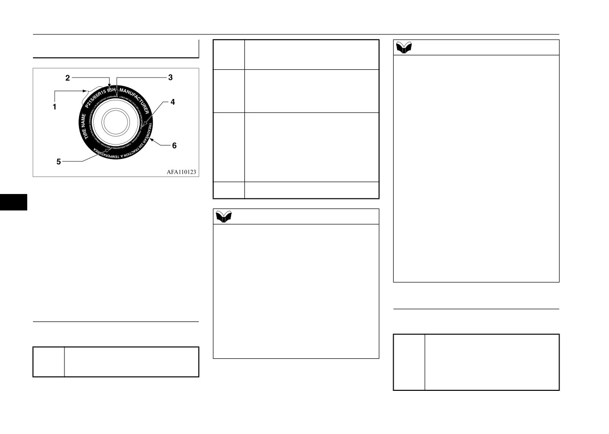
Tire Markings
Section width in millimeters
NOTE
215
(mm)
z
LT (Light Truck)
-metric tire
Aspect ratio in percent (%)
sizing is based on U.S.A. design
65
Ratio of section height to
standards. The size designation
section width of tire.
for LT-metric tires is the same as
for P-metric tires except for the
Construction code
letters “LT” that are molded into
• “R” means radial construc-
the sidewall preceding the size
R
tion.
designation.
• “D” means diagonal or bias
Example: LT235/85R16.
construction.
z
Temporary spare tires are high
1- Size Designation
15
Rim diameter in inches (in)
pressure
compact
spares
2- Service Description
9
designed for temporary emer-
3- Maximum Load
NOTE
gency use only. Tires designed
4- Maximum Pressure
z
European/Japanese metric tire
to this standard have the letter
5- U.S. DOT Safety
Standards
sizing is based on European/Jap-
“T” molded into the sidewall
Code (TIN)
anese design standards. Tires
preceding the size designation.
6- Treadwear, Traction
and Tem-
designed to these standards have
Example: T145/80D18 103M.
perature Grades
the tire size molded into the
sidewall beginning with the sec-
Service Description
Size Designation
tion width. The letter
“P” is
absent from this tire size desig-
EXAMPLE: 95H
EXAMPLE: P215/65R15
nation.
Load index
Example: 215/65R15 96H.
Passenger car tire size based
A numerical code associ-
P
95
on U.S.A. design standards
ated with the maximum load
a tire can carry.
9-14
Vehicle care and maintenance
Tires
EXAMPLE: DOT MA L9 ABCD
Speed symbol
WARNING
1504
A symbol indicating the
z Overloading of your tire is
Department of Transporta-
range of speeds at which a
dangerous. Overloading can
tion
tire can carry a load corre-
cause tire failure, affect vehi-
This symbol certifies that
sponding to its load index
cle handling, and increase
the tire is in compliance
under certain operating con-
your stopping distance. Use
DOT
with the U.S. Department
ditions.
tires of the recommended load
of Transportation tire safety
H
The maximum speed corre-
capacity for your vehicle.
standards, and is approved
sponding to the speed sym-
Never overload them.
for highway use.
bol should only be achieved
under specified operating
Code representing the tire
conditions. (i.e. tire pressure,
Maximum Pressure
MA
manufacturing location.
vehicle loading, road condi-
(2 digits)
9
tions and posted speed lim-
Maximum Pressure indicates the
Code representing the tire
its)
maximum permissible cold tire infla-
L9
size. (2 digits)
tion pressure for this tire.
ABCD
Code used by tire manufac-
Maximum Load
turer. (1 to 4 digits)
Tire Identification Number (TIN)
Number representing the
Maximum load indicates the maxi-
15
week in which the tire was
The TIN may be found on one or
mum load this tire is designed to
manufactured. (2 digits)
both sides of the tire but the date
carry.
code may only be on one side. Look
Number representing the
for the TIN on the outboard side of
04
year in which the tire was
tires as mounted on the vehicle. If the
manufactured. (2 digits)
TIN is not found on the outboard side
then you will find it on the inboard
side of the tire.
Vehicle care and maintenance
9-15
Tires
under controlled conditions on speci-
Treadwear, Traction and Temper-
Tire inflation pressures
fied government test surfaces of
ature Grades
N00939302082
asphalt and concrete. A tire marked
Proper tire inflation pressure is
C may have poor traction perfor-
Treadwear
essential for the safe and satisfactory
mance.
operation of your vehicle. The wrong
The treadwear grade is a comparative
tire pressure will cause problems in
rating based on the wear rate of the
Temperature
three major areas:
tire when tested under controlled
The temperature grades are A (the
conditions on a specified government
z
Safety
highest), B and C, representing the
test course. For example, a tire
Too little pressure increases flex-
tire’s resistance to the generation of
graded 150 would wear one and one-
ing in the tire and can cause tire
heat and its ability to dissipate heat
failure. Too much pressure can
half (11/2) times as well on the gov-
when tested under controlled condi-
9
cause a tire to lose its ability to
ernment course as a tire graded 100.
tions on a specified indoor laboratory
cushion shock. Objects on the
The relative performance of tires
test wheel. Sustained high tempera-
road and potholes could then
depends upon the actual conditions
ture can cause the material of the tire
cause tire damage that may result
of their use, however, and may depart
to degenerate and reduce tire life, and
in tire failure.
significantly from the norm due to
excessive temperature can lead to
z Economy
variations in driving habits, service
sudden tire failure. The grade C cor-
The wrong tire pressure can cause
practices and differences in road
responds to a level of performance
uneven wear patterns in the tire
characteristics and climate.
which all passenger car tires must
tread. These abnormal wear pat-
meet under the Federal Motor Vehi-
terns will reduce the tread life, and
Traction
cle Safety Standard No. 109. Grades
the tire will have to be replaced
B and A represent higher levels of
The traction grades, from highest to
sooner.
performance on the laboratory test
lowest, are AA, A, B and C. Those
Too little pressure also makes it
wheel than the minimum required by
grades represent the tire’s ability to
harder for the tire to roll, and this
law.
stop on wet pavement as measured
uses up more fuel.
9-16
Vehicle care and maintenance
Tires
z Ride comfort and vehicle stability
The recommended inflation pres-
Cold inflation pressure is measured
The superior riding experience
sures under normal driving condi-
after the vehicle has been parked for
built into your vehicle partly
tions should be used for the tires
at least three hours or is driven less
depends on the correct tire pres-
listed below.
than
1 mile (1.6 km) after having
sure. Too much pressure gives an
been parked for three hours.
uncomfortable and jarring ride.
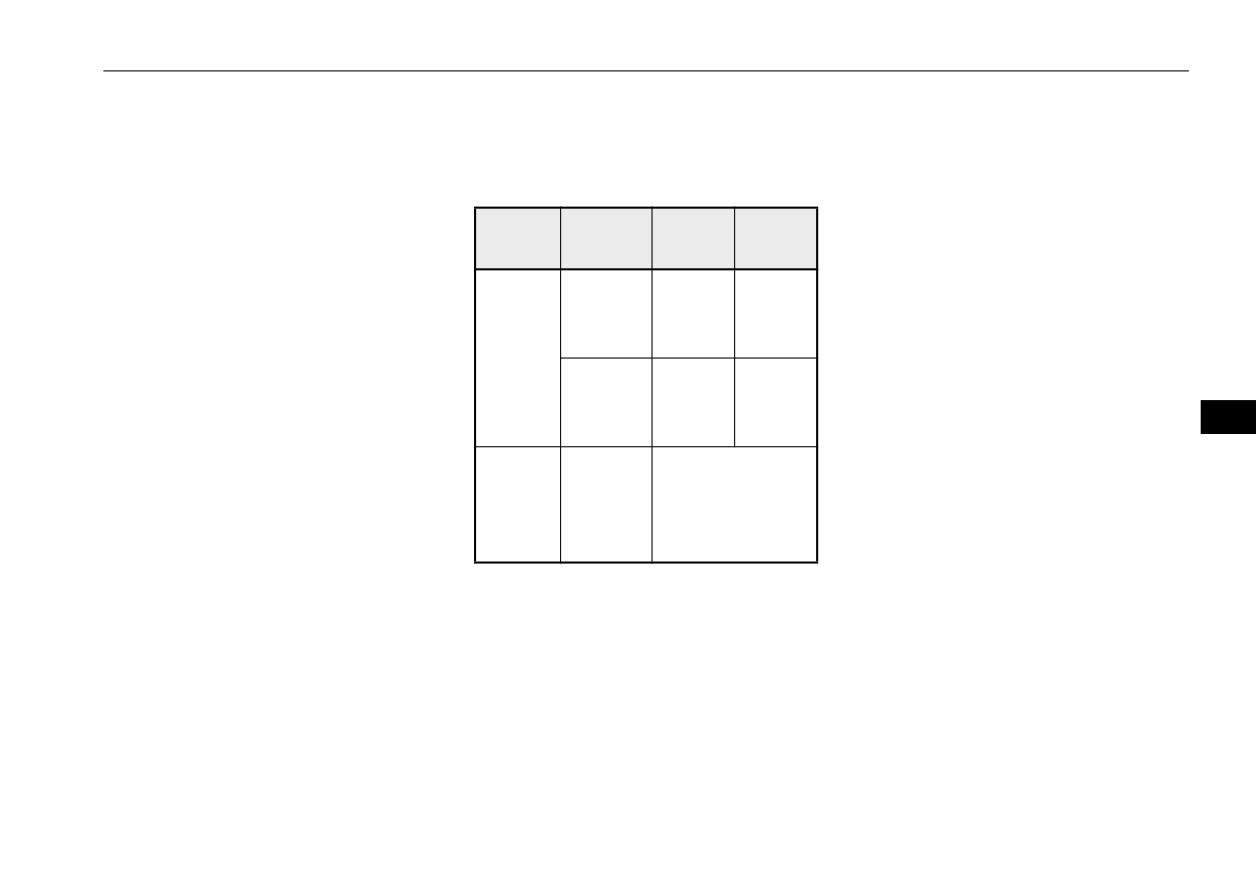
Tire
Cold inflation pressure must not go
Item
Front
Rear
Too little pressure feels as if your
size
above the maximum values molded
vehicle is slow to respond.
270
270
into the tire sidewall. After driving
165/65R
Unequal tire pressures can make
kPa,
kPa,
several miles, your tire inflation pres-
14
steering your vehicle uneven and
39 psi
39 psi
sure may increase 2 to 6 psi (14 to
Nor-
unpredictable.
41 kPa) from the cold inflation pres-
mal tire
240
240
175/55R
sure. Do not let air out of the tires to
kPa,
kPa,
The tire pressure for your vehicle
15
get back to the specified cold pres-
9
35 psi
35 psi
under normal driving conditions is
sure, or your tires will be too low.
listed on the placard attached to the
Com-
Check your tires each time you
driver’s door sill.
pact
T115/70
refuel. If one tire looks lower than
420 kPa, 60 psi
(Refer to “Tire and loading informa-
spare
D14
the others, check the pressure for all
tion placard” on page 11-3.)
wheel
of them.
You should also take the following
Tire pressures should be checked,
safety precautions:
and adjusted if necessary, at least
once a month.
z Keep your tires inflated to the rec-
Pressures should be checked more
ommended pressures. (See the tire
often whenever weather temperatures
and loading information placard
change severely, because tire pres-
attached to the driver’s door sill.)
sures change with outdoor tempera-
z Stay within the recommended
tures. The pressures listed are always
load limits.
“cold inflation pressure”.
Vehicle care and maintenance
9-17
Tires
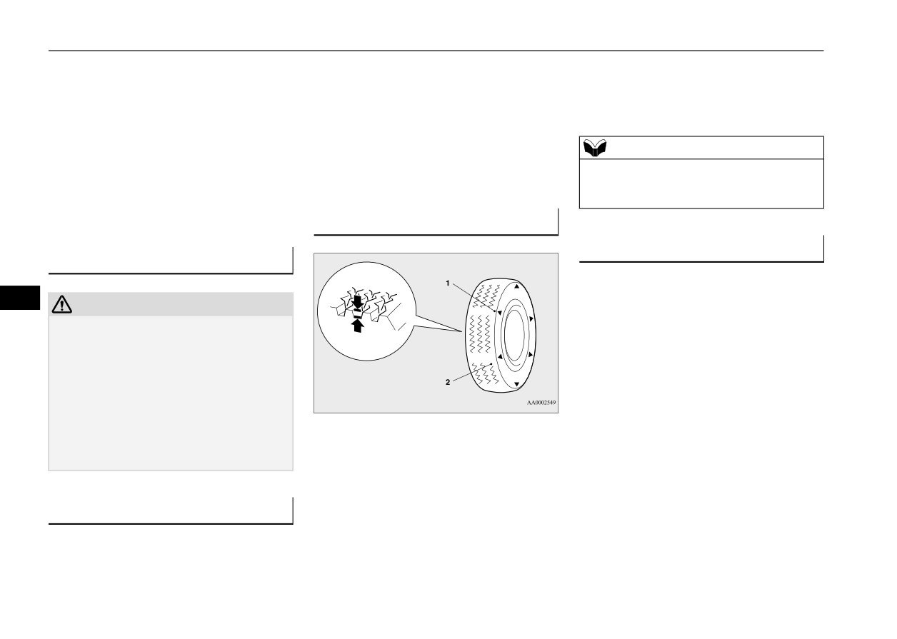
z Make sure that the weight of any
z Check tire pressures regularly.
tire tread is worn down to 1/16 inch (1.6
mm).
load in your vehicle is evenly dis-
z Have regular maintenance done
When the bands appear next to one another in
tributed.
on the wheel balance and front
two or more places, replace your tires.
z Drive at safe speeds.
and rear suspension alignment.
z After filling your tires to the cor-
z Rotate your tires regularly as
NOTE
rect pressure, check them for dam-
described in the
“Tire
rotation”
z Tire wear indicators can have different marks
age and air leaks. Be sure to
section on page 9-18.
and locations depending on the tire manufac-
reinstall the caps on the valve
turer.
stems.
Tread wear indicator
N00939801240
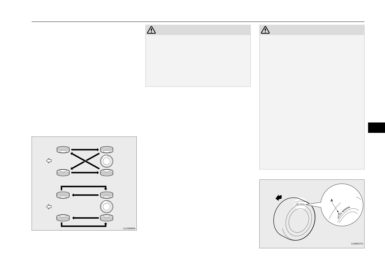
Tire rotation
Replacing tires and wheels
N00939901586
N00939601512
To even out the wear on your tires
9
CAUTION
and make them last longer, Mitsubi-
z Avoid using different size tires from the one
shi Motors Corporation recommends
listed and the combined use of different
that you rotate your tires at the mile-
types of tires, as this can affect driving
safety.
age listed in the “WARRANTY AND
Refer to “Tires and wheels” on page 11-5.
MAINTENANCE MANUAL”.
z Only Mitsubishi Motors Genuine wheels
However, the timing for tire rotation
should be used.
may vary according to your vehicle
Use of another type of wheel risks air leaks
1- Location of the tread wear indicator
and sensor damage, as it will not be possible
2- Tread wear indicator
condition, road surface conditions,
to install the tire pressure sensor properly.
and your own personal driving hab-
Tread wear indicators are built into the origi-
its. Any time you notice unusual
nal equipment tires on your vehicle to help
wear, rotate your tires as soon as pos-
Tire maintenance
you know when your tires should be replaced.
sible.
N00939701207
Many states have laws requiring that you
The following maintenance steps are
replace your tires at this point.
When rotating tires, check for
These indicators are molded into the bottom
recommended:
uneven wear, damage, and wheel
of the tread grooves and will appear when the
9-18
Vehicle care and maintenance
Tires
alignment. Abnormal wear is usually
CAUTION
CAUTION
caused by a wrong tire pressure,
z
A compact spare tire can be
z
If the tires have arrows (A) indi-
wheels that are not aligned properly,
installed temporarily in place of
cating the correct direction of
wheels that are out-of-balance, or
a tire that has been removed dur-
rotation, swap the front and rear
severe braking.
ing the tire rotation. However, it
tires on the left-hand side of the
Check with an authorized Mitsubishi
must not be included in the regu-
vehicle and the front and rear
Motors dealer or a repair facility of
lar tire rotation sequence.
tires on the right-hand side of
your choice to find out the reason for
the vehicle separately. Keep
uneven tread wear.
each tire on its original side of
the vehicle. When installing the
The first tire rotation is the most
tires, make sure the arrows point
important one. It will allow all your
in the direction in which the
tires to wear evenly.
9
wheels will turn when the vehi-
cle moves forward. Any tire
Tires that do not have arrows showing rotation
direction
whose arrow points in the wrong
direction will not perform to its
Front
full potential.
Tires that have arrows showing rotation direc-
tion
Front
Front
Vehicle care and maintenance
9-19
Clutch pedal free play (if so equipped)
If the free play is not within these limits, take
CAUTION
Tire chains
your vehicle to an authorized Mitsubishi
z Avoid the combined use of dif-
N00940100116
Motors dealer or a repair facility of your
ferent types of tires. Using dif-
choice for adjustment.
CAUTION
ferent types of tires can affect
z Tire chains cannot be used on your vehicle.
vehicle performance and safety.
The clearance between the chains and the
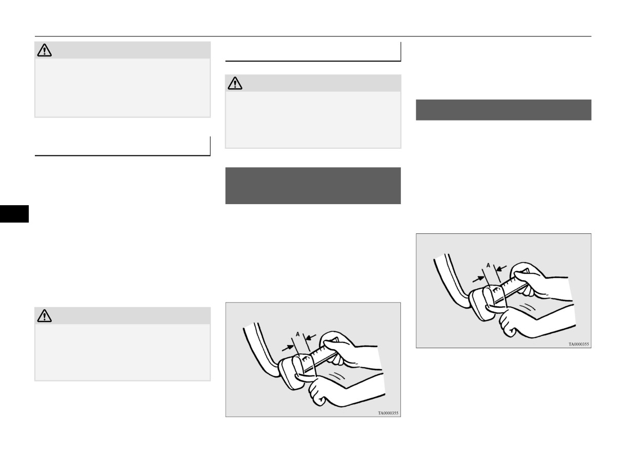
Brake pedal free play
body is not sufficient to allow proper clear-
N00940300336
ance, and the vehicle body might be dam-
To check the brake pedal free play (A), turn
aged.
Snow tires
off the engine and press the brake pedal sev-
N00940001499
eral times with your foot. Then press the
pedal down with your fingers until you first
In some areas of the country, snow tires are
Clutch pedal free play (if so
feel resistance.
required for winter driving. If snow tires are
required in your area, you must choose snow
equipped)
Brake pedal free play:
tires of the same size and type as the original
N00940200090
9
.1 to .3 inch (3 to 8 mm)
tires provided with your vehicle. Snow tires
To check the clutch pedal free play (A), turn
should also be installed on all four wheels.
off the engine and press the pedal until you
Otherwise your safety and vehicle handling
feel resistance.
can be reduced.
Even where laws may permit it, snow tires
Clutch pedal free play:
should not be operated at sustained speeds
.4 to .6 inch (11 to 16 mm)
over 75 mph (120 km/h).
CAUTION
z Only Mitsubishi Motors Genuine wheels
should be used.
Use of another type of wheel risks air leaks
and sensor damage, as it will not be possible
If the free play is not within these limits, take
to install the tire pressure sensor properly.
your vehicle to an authorized Mitsubishi
Motors dealer or a repair facility of your
choice for adjustment.
9-20
Vehicle care and maintenance
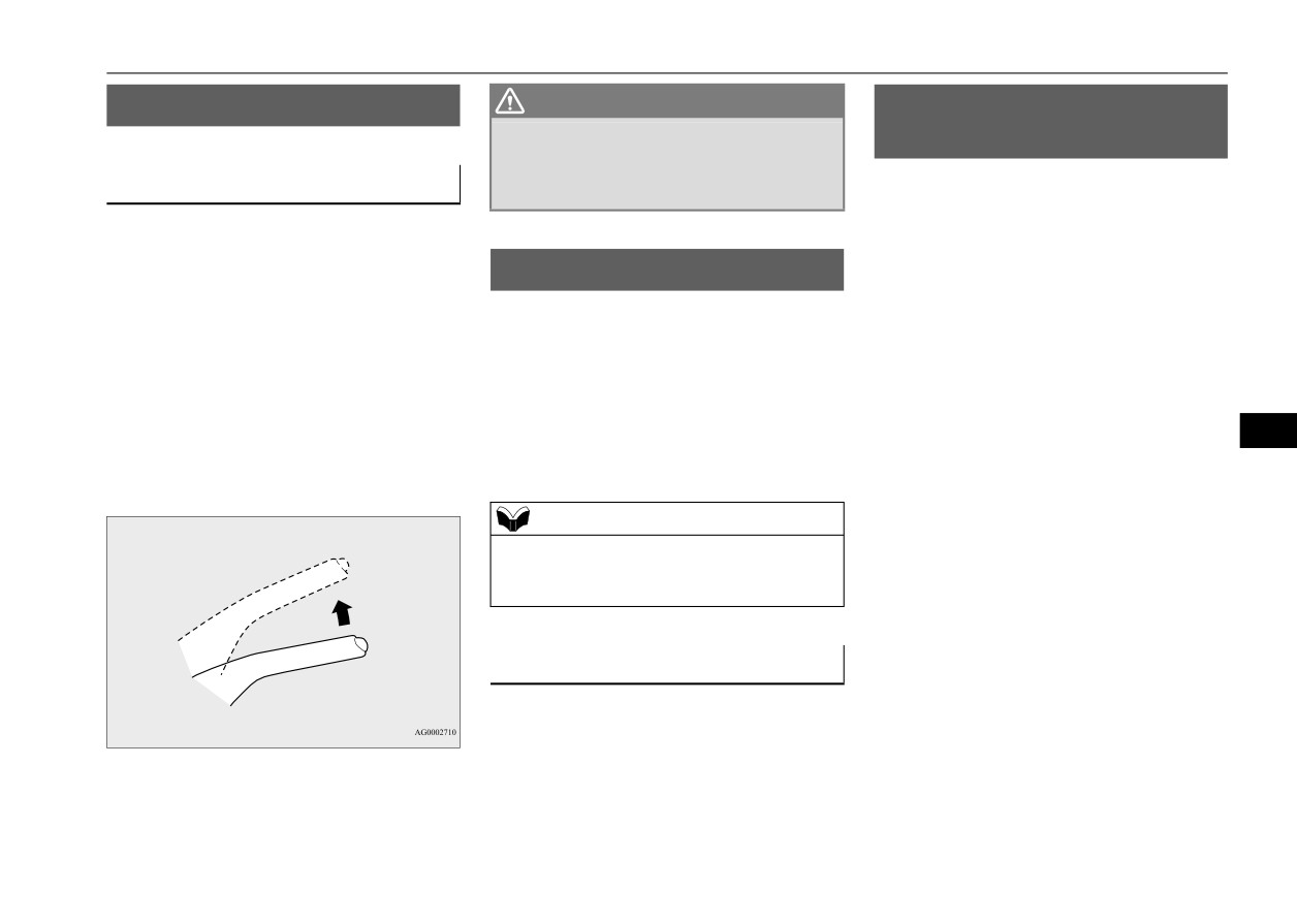
Parking brake
Parking brake
WARNING
Emission-control system
N00940400252
z Continued operation of the vehicle with
maintenance
the parking brake lever out of adjustment
N00940801354
may result in the vehicle moving when
Parking brake lever stroke
unattended.
Your vehicle is equipped with an emission-
control system that meets all the requirements
Check the parking brake lever travel occa-
of the U.S. Environmental Protection
sionally. To check this, pull the lever up
Agency. The emission-control system is
slowly and count the number of clicks of the
Wiper blades
made of:
ratchet.
N00940701223
Check the wiper blades occasionally. Clean
z a positive crankcase ventilation system
Parking brake lever stroke:
them regularly to remove deposits of salt and
z an evaporative emission-control system
7 to 9 notches (clicks)
road film. Use a sponge or cloth and a mild
z an exhaust emission-control system
(Parking brake adjustment when pulled with
detergent or non-abrasive cleaner to clean the
the force of 200 N)
blades and glass areas.
To be sure the emission-control system works
9
Replace the blades if they continue to streak
properly, have your vehicle inspected and
Also check to see if the lever stays gripped by
or smear.
maintained by an authorized Mitsubishi
the ratchet after pulling.
Motors dealer or a repair facility of your
choice. This should be done at the time or
NOTE
mileage specified in the “WARRANTY AND
z Do not run the wipers on dry glass for a long
MAINTENANCE MANUAL”.
time. This wears out the rubber and can
scratch the glass.
These, and all the other “general” mainte-
nance services listed in this manual, need to
be performed to keep your vehicle running
properly and reliably.
During cold weather
You should also have an inspection and ser-
vice any time you suspect a malfunction.
If the blades are frozen to the windshield, do
not operate the wipers until the ice has melted
and the blades are freed, otherwise the wiper
motor may be damaged.
Vehicle care and maintenance
9-21
General maintenance
high heat sources such as the exhaust mani-
NOTE
Fuel hoses
fold.
z To meet government regulations and pro-
N00941000040
mote cleaner air, your vehicle is equipped
Check the hose surfaces for any heat and
with an onboard diagnostic system (OBD).
WARNING
mechanical damage, hard and brittle rubber,
The engine electronic control module that
z If you see a fuel leak or if you smell fuel,
cracking, tears, cuts and abrasions. Pay spe-
controls OBD functions stores various data
do not run the engine. Any spark (includ-
cial attention to the hoses closest to high heat
(especially about the exhaust emissions).
ing from the ignition), flame or smoking
sources such as the exhaust manifold. Check
This data will be erased if the battery cable is
material could cause an explosion or fire.
disconnected, which could make a rapid
all the hose connections, such as clamps and
Call an authorized Mitsubishi Motors
diagnosis difficult. Do not disconnect the
couplings, to make sure they are secure and
dealer or a repair facility of your choice
battery cable when the engine malfunction
that there are no leaks. If you see any wear or
for assistance.
indicator (“SERVICE ENGINE SOON”) is
damage, replace the hoses immediately.
ON.
Evaporative emission control
Intake valve clearance
N00950100050
system (except evaporative
9
Spark plugs
Have the valve clearance checked at an
emission canister)
N00940900228
authorized Mitsubishi Motors dealer at the
N00941400187
Spark plugs must fire properly for good
mileage specified in the “WARRANTY AND
If the fuel-vapor vent line is clogged or dam-
engine performance and emission-control.
MAINTENANCE MANUAL”.
aged, the fuel-vapor mixture will escape, pol-
Do not reuse them by cleaning or regapping.
If the engine sounds abnormally loud, have
luting the air.
Change them at the mileage listed in the
adjustments made by an authorized
Have the system checked at an authorized
“WARRANTY AND MAINTENANCE
Mitsubishi Motors dealer.
Mitsubishi Motors dealer at the mileage spec-
MANUAL”.
ified in the “WARRANTY AND MAINTE-
Fuel system (tank, pipe line and
NANCE MANUAL”.
NOTE
z Use the spark plugs listed under
“Engine
connection, and fuel tank filler
specifications” on page 11-5 or plugs that are
cap)
General maintenance
exactly the same. Other plugs could cause
N00941500292
N00941300173
engine damage, performance problems or
Check these regularly for damage or leaks in
The next pages list the maintenance service
radio noise.
the fuel lines and connections. Check the fuel
recommended by Mitsubishi Motors Corpo-
tank filler cap for damage or looseness. Pay
ration. In addition to the general maintenance
special attention to the fuel lines closest to
that needs to be performed at the times listed,
9-22
Vehicle care and maintenance
General maintenance
there are other parts which do not usually
z The underside or rear of the vehicle is
Ball joint, steering linkage seals
need regular maintenance.
damaged
But, if any of these parts stops working prop-
and drive shaft boots
erly, your vehicle performance could suffer.
N00941800077
Also check the exhaust system each time the
Have these items checked if you notice a
Check the following parts for damage and
vehicle is raised for lubrication, oil changes,
problem with them.
grease leaks:
or required service. Any open seams or loose
connections could let dangerous exhaust
If you have any questions, see your autho-
z Ball joint boots of the front suspension
fumes seep into the luggage and passenger
rized Mitsubishi Motors dealer for assistance.
and steering linkage
compartments.
z Bellows on both ends of the drive shaft
Disc brake pads
Check for any of the following
N00941600059
Exhaust system
conditions:
Good brakes are essential for safe driving.
N00942200111
z Check for holes or exhaust gas leaks
Check the brake pads for wear. For good
WARNING
caused by corrosion or damage.
braking performance, replace the brake pads
9
z Carbon monoxide gas from your vehicle’s
z Check the joints and connections for
with the same type pads as the originals.
exhaust is poisonous. Breathing these
looseness or exhaust gas leaks.
fumes can cause unconsciousness or death.
z Check the rubber hangers and brackets for
Brake hoses
damage.
N00941700076
The best way to keep carbon monoxide gas
Brake hoses and tubing should be checked
from entering inside your vehicle is to have
Hood lock release mechanism
for:
the engine exhaust system properly serviced.
and safety catch
Have a competent mechanic inspect the com-
z Severe surface cracking, scuffing or worn
N00942500127
plete exhaust system and nearby body areas
spots. If the fabric casing of the hose is
for broken, damaged, deteriorated, or mispo-
The hood lock release mechanism and hood
showing through any cracks or worn spots
sitioned parts if you notice any of the follow-
safety catch should be checked, cleaned, and
in the rubber hose cover, the hose should
ing:
oiled when needed for easy movement and to
be replaced. The brakes can fail if the
prevent rust and wear. Use Multipurpose
hose wears through.
z A change in the sound of the exhaust sys-
Grease NLGI Grade 2 sparingly for all sliding
z Improper installation may cause twisting,
tem
parts of the hood latch and release lever.
or wheel, tire or chassis interference.
z The smell of exhaust fumes inside the
Work the grease into the hood lock mecha-
vehicle
Vehicle care and maintenance
9-23
For cold and snowy weather
nism until all the movable surfaces are cov-
snow off the vehicle and a plastic scraper for
individual circuit is equipped with a fuse. The
ered.
the windshield, side and rear window are also
fuse blocks are located in the passenger com-
Also, put a light coat of the same grease on
useful.
partment and in the engine compartment.
the safety catch wherever moving parts touch.
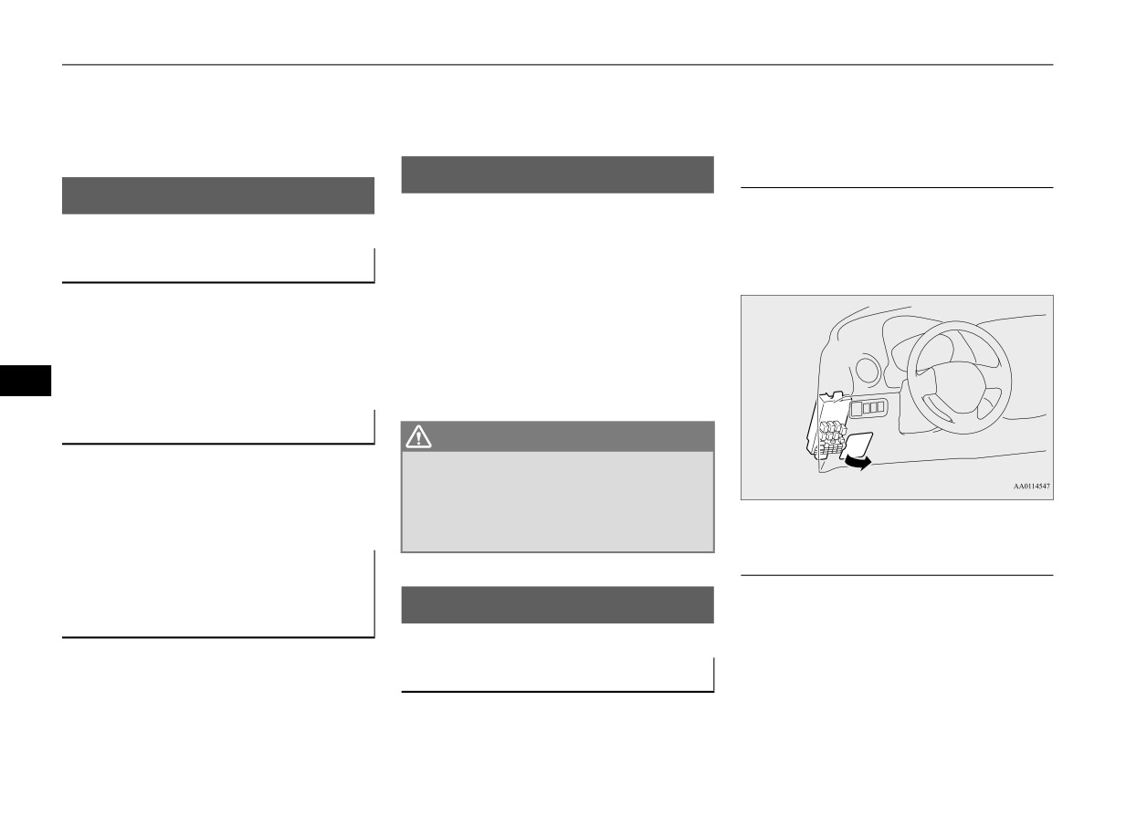
Passenger compartment
Fusible links
For cold and snowy weather
N00942700305
N00942600102
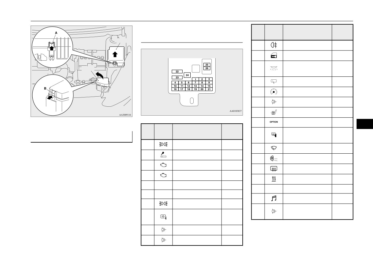
The fuse block in the passenger compartment
The fusible links will melt to prevent a fire if
is located in front of the driver’s seat at the
a large current attempts to flow through cer-
position shown in the illustration.
Ventilation slots
tain electrical systems.
In case of a melted fusible link, see your
authorized Mitsubishi Motors dealer or a
The ventilation slots in front of the wind-
repair facility of your choice for inspection
shield should be brushed clear after a heavy
and replacement.
snowfall so that the operation of the heating
For the fusible links, please refer to “Fuse
and ventilation systems will not be impaired.
9
load capacities” on page 9-25.
Weatherstripping
WARNING
z Fusible links must not be replaced by any
To prevent freezing of the weatherstripping
other device. Failing to fit the correct fus-
on the doors, engine hood, etc., they should
ible link may result in fire in the vehicle,
be treated with silicone grease.
property destruction and serious or fatal
injuries at any time.
Engine compartment
Additional equipment (For
regions where snow is encoun-
Fuses
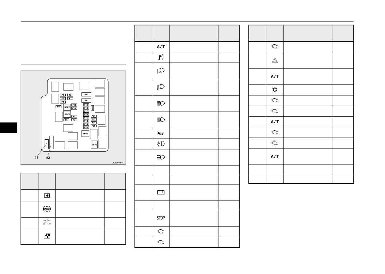
In the engine compartment, the fuse block is
tered)
N00942800902
located as shown in the illustration.
While pressing the tab (A or B), pull up the
It is a good idea to carry a shovel or a short-
cover.
Fuse block location
handled spade in the vehicle during the win-
ter so that you can clear away snow if you get
To prevent damage to the electrical system
stranded. A small hand-brush for sweeping
from short-circuiting or overloading, each
9-24
Vehicle care and maintenance
Fuses
Passenger compartment fuse loca-
Sym-
Capac-
No.
Electrical system
bol
ity
tion table
Type A
11
Rear fog light
10 A
12
Door lock
15 A
Interior light (Dome
Type B
13
15 A
light)
14
Rear window wiper
15 A
15
Gauges
7.5 A
16
Relay
7.5 A
17
Heated seats
20 A
18
Option
10 A
9
Sym-
Capac-
No.
Electrical system
Heated outside rear-
bol
ity
19
7.5 A
Fuse load capacities
view mirrors
N00954801342
1
Tail light (left)
7.5 A
20
Windshield wiper
20 A
This fuse list shows the names of the electri-
2
Cigarette lighter
15 A
cal systems and their fuse capacities.
21
Back-up light
7.5 A
There are spare fuses in the fuse block in the
3
Ignition coil
10 A
22
Defogger
30 A
engine compartment. Always replace a blown
4
Starter motor
7.5 A
fuse with one of the same capacity as the
23
Heater
30 A
5
—
—
—
original.
24
—
—
—
6
—
—
—
25
Radio
10 A
7
Tail light (right)
7.5 A
Electronic con-
26
15 A
Outside rearview
trolled unit
8
7.5 A
mirrors
z Some fuses may not be installed on your
9
Engine control unit
7.5 A
vehicle, depending on the vehicle model
10
Control unit
7.5 A
or specifications.
Vehicle care and maintenance
9-25
Fuses
z The table above shows the main equip-
Sym-
Capac-
Sym-
Capac-
ment corresponding to each fuse.
No.
Electrical system
No.
Electrical system
bol
ity
bol
ity
BF1
DC-DC (P/T)
30 A
F15
Alternator
7.5 A
Engine compartment fuse location
BF2
DC-DC (AUDIO)
30 A
Hazard warning
table
F16
10 A
flasher
Headlight (low
F1
10 A
beam) (left)
Automatic trans-
Type A
F17
15 A
axle
Headlight (low
F2
10 A
beam) (right)
F18
Air conditioning
10 A
Headlight (high
F19
ETV
15 A
F3
10 A
beam) (left)
F20
Starter
7.5 A
Headlight (high
F4
10 A
beam) (right)
F21
CVT oil/pump
15 A
9
F5
Horn
10 A
F22
Fuel pump
15 A
F6
Front fog lights
15 A
F23
Engine
20 A
Daytime running
Automatic trans-
F7
10 A
F24
7.5 A
lights
axle
F8
—
—
—
#1
—
Spare fuse
20 A
Sym-
Capac-
#2
—
Spare fuse
30 A
No.
Electrical system
F9
—
—
—
bol
ity
Battery current
F10
7.5 A
*: Fusible link
SBF1
Radiator fan motor
40 A*
sensor
Anti-lock braking
F11
—
—
—
z Some fuses may not be installed on your
SBF2
30 A*
system
vehicle, depending on the vehicle model
Stop lights (Brake
F12
15 A
or specifications.
SBF3
Ignition switch
40 A*
lights)
z The table above shows the main equip-
F13
Ignition coil
7.5 A
Power window
ment corresponding to each fuse.
SBF4
40 A*
control
F14
Engine control
7.5 A
9-26
Vehicle care and maintenance
Fuses
15 A: Cigarette lighter
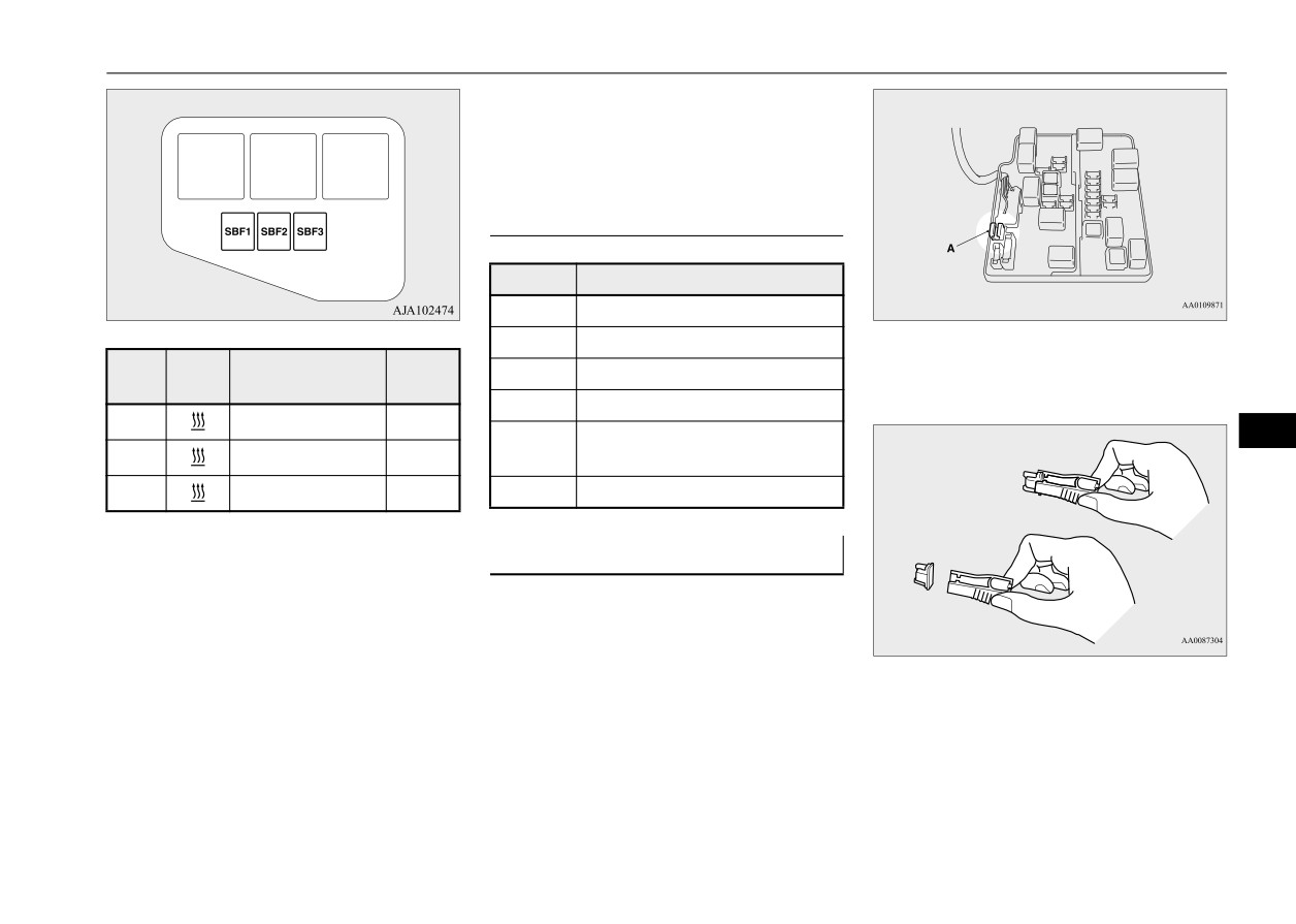
Type B
When using a substitute fuse, replace with a
fuse of the correct capacity as soon as possi-
ble.
Identification of fuse
Capacity
Color
7.5 A
Brown
10 A
Red
Sym-
Capac-
3. Clamp it on the fuse you wish to remove,
No.
Electrical system
15 A
Blue
bol
ity
and pull the fuse straight out from the fuse
20 A
Yellow
block.
SBF1
PTC heater
40 A*
Green (fuse type) /Pink (fusible
9
30 A
SBF2
PTC heater
40 A*
link type)
SBF3
PTC heater
40 A*
40 A
Green (fusible link type)
*: Fusible link
Fuse replacement
N00954900131
z Some fuses may not be installed on your
1. Before replacing a fuse, always turn off
vehicle, depending on the vehicle model
the electrical item concerned to the fuse
or specifications.
and turn the ignition switch to the “OFF”
z The table above shows the main equip-
position or put the operation mode in
ment corresponding to each fuse.
4. Use the fuse location diagrams and the
OFF.
matching tables, to check the fuse that is
2. There is a fuse remover (A) in the engine
The fuse block does not contain spare 7.5 A,
related to the problem. If the fuse is not
compartment fuse block.
10 A or 15 A fuses. If one of these fuses
blown, something else must be causing
burns out, substitute with the following fuse.
the problem. Have the system inspected
7.5 A: Outside rearview mirrors
by your authorized Mitsubishi Motors
10 A: Option
dealer or a repair facility of your choice.
Vehicle care and maintenance
9-27
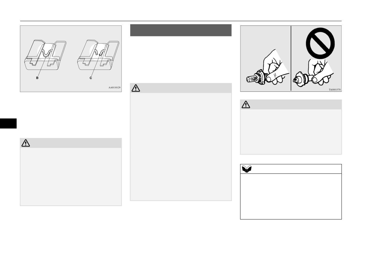
Replacement of light bulbs
Replacement of light bulbs
N00942901362
Before replacing the bulb, be sure the light is
off. Do not touch the glass part of the new
bulb with your bare fingers; the oil from your
skin will stay on the glass and dim or destroy
the bulb when it gets hot.
CAUTION
z
Bulbs are extremely hot immediately after
B- Fuse is OK
being turned off.
C- Blown fuse
CAUTION
When replacing the bulb, wait for it to cool
z
Do not install commercially available LED-
sufficiently before touching it. You could
type bulbs.
5. Insert a new fuse of the same capacity
otherwise be burned.
9
Commercially available LED-type bulbs
securely into the appropriate slot.
z
Handle halogen light bulb with care. The gas
could adversely affect the operation of the
inside halogen light bulb is highly pressur-
vehicle, such as by preventing the lights and
ized, so dropping, knocking, or scratching a
CAUTION
other vehicle equipment from operating
halogen light bulb can cause it to shatter.
properly.
z Never use a fuse with a capacity greater than
z
Never hold the halogen light bulb with a bare
the one listed or any substitute, such as wire,
hand, dirty glove, etc.
foil etc. This would cause the circuit wiring
The oil from your hand could cause the bulb
to heat up and could cause a fire.
to break the next time the headlights are
NOTE
z If the replacement fuse blows again after a
used.
z
If you are unsure of how to carry out the
short time, have the electrical system
If the glass surface is dirty, clean it with
work as required, it is recommended that
checked by an authorized Mitsubishi Motors
alcohol and let it dry completely before
these procedures be carried out by an autho-
dealer or a repair facility of your choice to
installing the bulb.
rized Mitsubishi Motors dealer or a repair
find and correct the cause.
facility of your choice.
z
Be careful not to scratch the vehicle body
when removing a light and lens.
9-28
Vehicle care and maintenance
Replacement of light bulbs
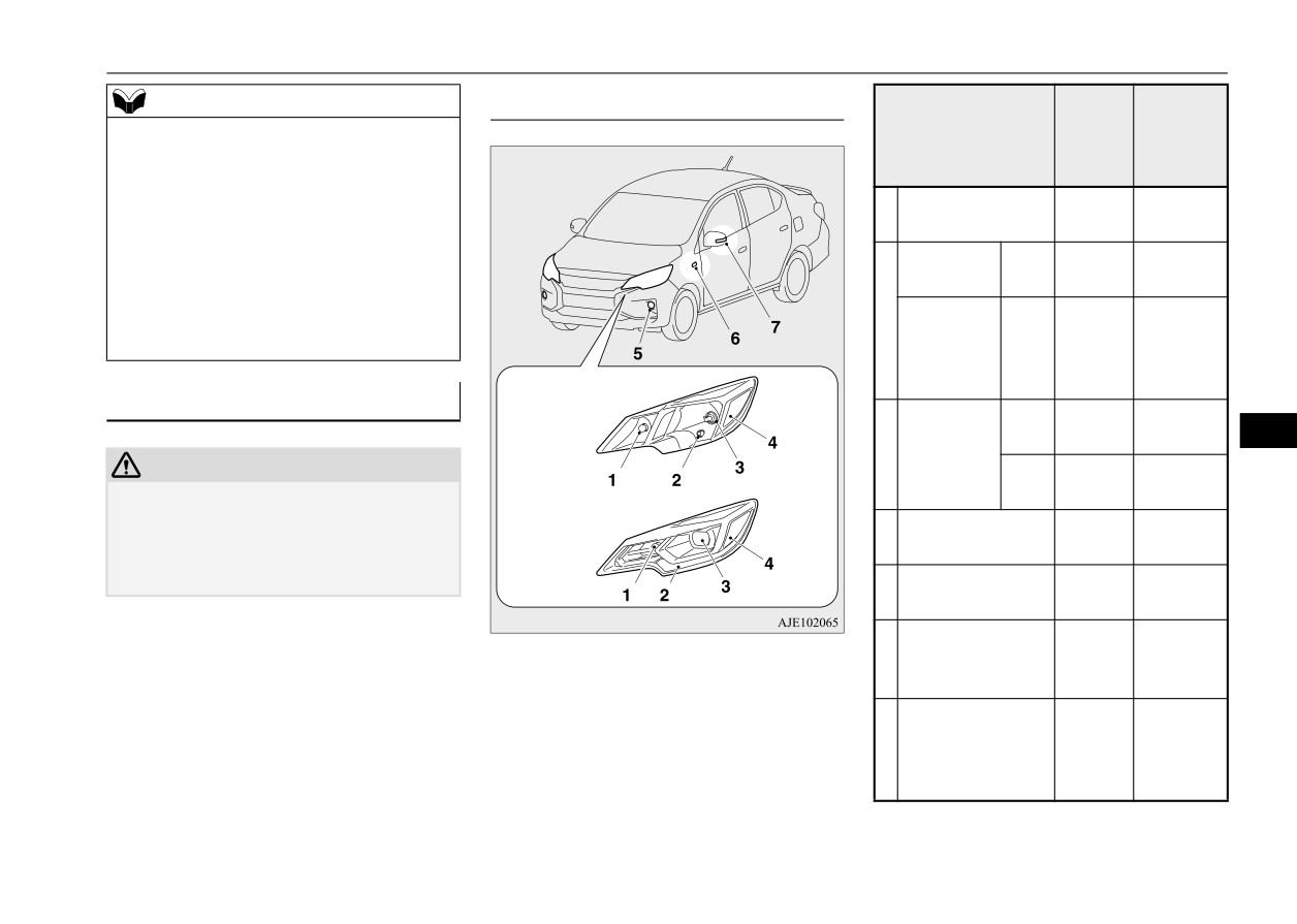
Outside
ANSI
NOTE
N00950302232
Watt-
Trade No.
z When it rains, or when the vehicle has been
Description
age
or Bulb
washed, the inside of the lens sometimes
Front
type
becomes temporarily foggy. This is the same
phenomenon as when window glass mists up
Front turn signal
on a humid day, and does not indicate a func-
1
27 W
#1156NA
light
tional problem.
When the light is switched on, the heat will
Parking
Type
5 W
W5W
remove the fog. However, if water gathers
light
A
inside the light, please have it checked by an
Parking
authorized Mitsubishi Motors dealer or a
2
light/Day-
Type
repair facility of your choice.
—
—
time run-
B
Type A
ning light
Bulb location and capacity
Type
N00943001230
60/55 W
HB2
A
9
3
Headlight
CAUTION
Type
—
—
z
When replacing a bulb, be sure to use a new
B
Type B
bulb of the same type, wattage, and color.
Front side-marker
If you install a different bulb, the bulb could
4
5 W
W5W
light
malfunction or fail to come on and could
lead to a vehicle fire.
Front fog light (if
5
19 W
H16
so equipped)
Side turn signal
Type A:
Halogen headlights type
6
light (on fender, if
5 W
—
Type B:
LED headlights type
so equipped)
Side turn signal
light (on outside
7
—
—
rearview mirror, if
so equipped)
Vehicle care and maintenance
9-29
Replacement of light bulbs
ANSI
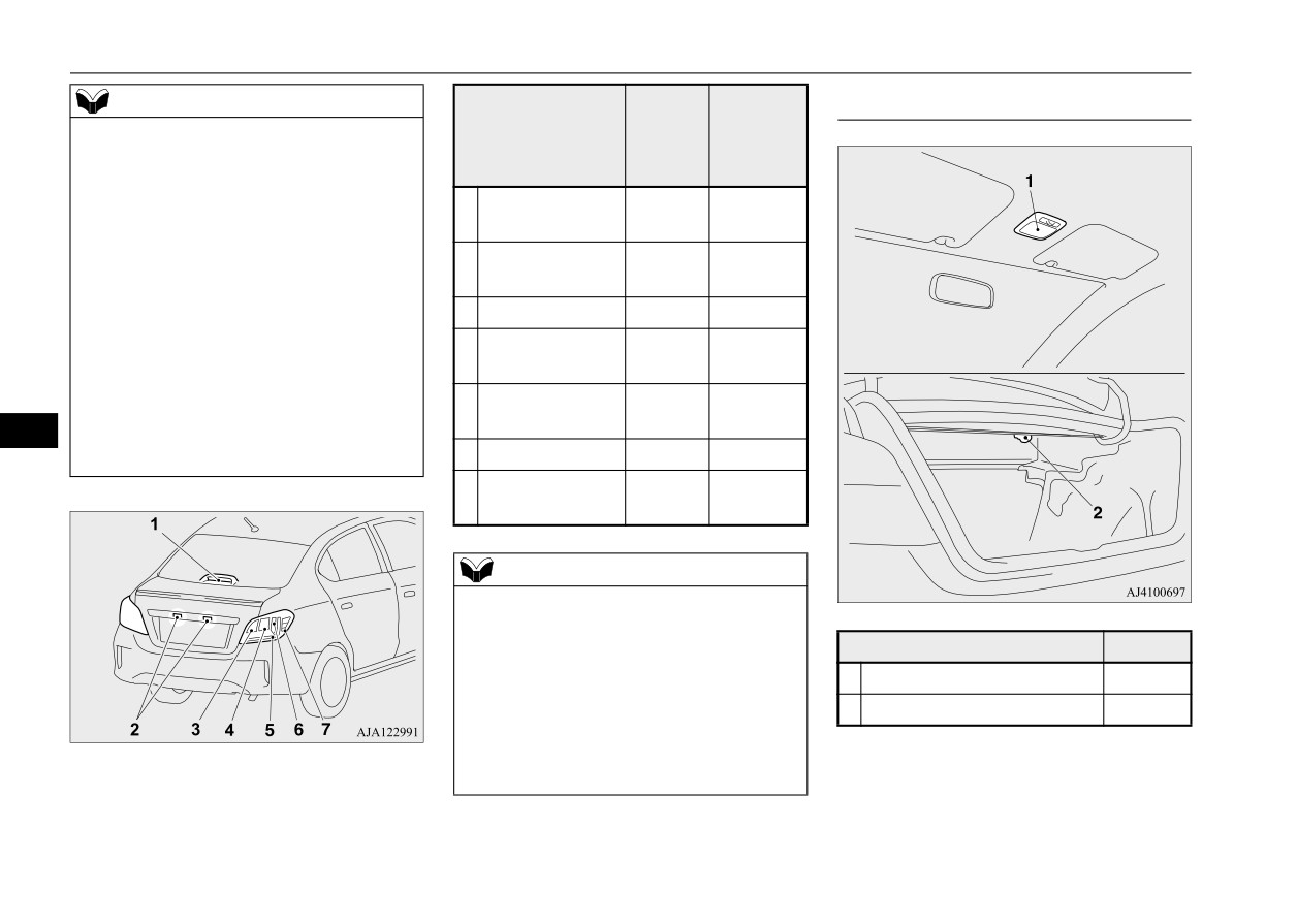
Inside
NOTE
trade No.
N00950401858
z
It is not possible to repair or replace only the
Item
Wattage
or bulb
bulb for the side turn signal light (on fender).
Check with an authorized Mitsubishi Motors
type
dealer or a repair facility of your choice
High-mounted
when the light needs to be repaired or
1
—
—
stop light
replaced.
z
The following lights use an LED-type bulb.
License plate
2
5 W
W5W
Check with an authorized Mitsubishi Motors
light
dealer or a repair facility of your choice
3
Back-up light
16 W
W16W
when either light needs to be repaired or
replaced.
Rear turn signal
4
21 W
PY21W
• Headlight (Type B)
light
• Parking light/Daytime running light (Type
Tail and stop
5
—
—
B)
light
9
• Side turn signal light (on outside rearview
6
Stop light
—
—
mirror)
Rear side-marker
7
—
—
light
Rear
NOTE
z
The following lights use an LED-type bulb.
Check with an authorized Mitsubishi Motors
dealer or a repair facility of your choice
Item
Wattage
when either light needs to be repaired or
1
Dome light
8 W
replaced.
• High-mounted stop light
2
Trunk room light
5 W
• Tail and stop light
• Stop light
• Rear side-marker light
9-30
Vehicle care and maintenance
Replacement of light bulbs
3. To install the bulb, perform the removal
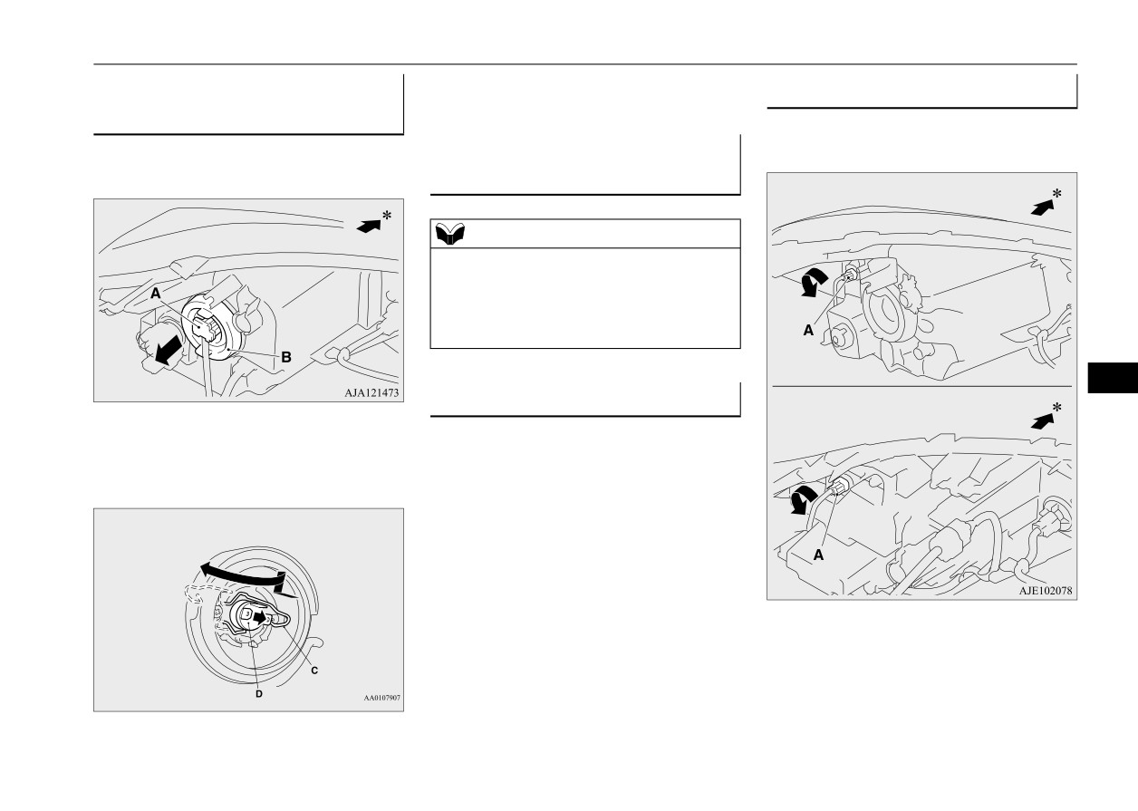
Headlights (Halogen headlights
Front side-marker lights
steps in reverse.
type)
N00917301825
1. Turn the socket (A) counterclockwise to
N00901801317
Headlights (LED headlights
remove it.
1. Pull out the connector
(A), and then
remove the sealing cover (B).
type)
Halogen headlights type
N00901901204
NOTE
z The headlights use an LED-type bulb.
Check with an authorized Mitsubishi Motors
dealer or a repair facility of your choice
when the light needs to be repaired or
replaced.
9
Headlight aim adjustment
LED headlights type
*- Front of the vehicle
N00943200352
The alignment of the headlights should be
2. Unhook the spring (C), which secures the
checked by an authorized Mitsubishi Motors
bulb, and then remove the bulb (D).
dealer or a repair facility of your choice.
*- Front of the vehicle
Vehicle care and maintenance
9-31
Replacement of light bulbs
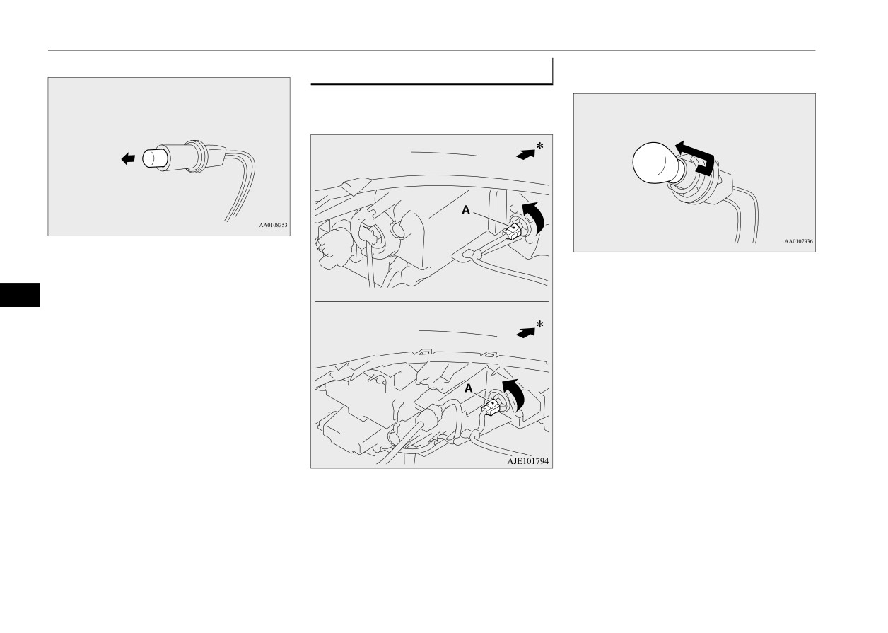
2. Pull the bulb out of the socket.
2. Remove the bulb from the socket by turn-
Front turn signal lights
ing it counterclockwise while pressing in.
N00943401537
1. Turn the socket (A) counterclockwise to
remove it.
Halogen headlights type
3. To install the bulb, perform the removal
3. To install the bulb, perform the removal
steps in reverse.
steps in reverse.
9
LED headlights type
*- Front of the vehicle
9-32
Vehicle care and maintenance
Replacement of light bulbs
4. Turn the bulb
(E) counterclockwise to
Parking lights (Halogen head-
Front fog lights (if so equipped)
remove it.
lights type)
N00943602057
N00917301838
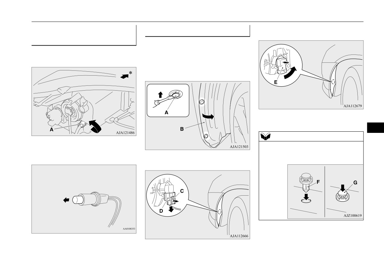
1. To create enough work space, turn the
1. Turn the socket (A) counterclockwise to
steering wheel all the way in the direction
remove it.
opposite to the side you wish to replace.
2. Remove the clips (A) to turn up the cover
(B).
5. To install the bulb, perform the removal
steps in reverse.
9
NOTE
*- Front of the vehicle
z When refitting each of the clips, first insert
part (F) of the clip into the hole and then
2. Pull the bulb out of the socket.
3. While pressing the tab (C), pull out the
press part (G) into it.
connector (D).
3. To install the bulb, perform the removal
steps in reverse.
Vehicle care and maintenance
9-33