Mitsubishi ASX (2020 year). Manual in english - page 12

Rear-view camera*
Location of rear-view camera
NOTE
The rear-view camera (A) is integrated into
Because the rear-view camera has a special
z
the part near the tailgate handle.
lens, the lines on the ground between park-
ing spaces may not look parallel on the
screen.
z
In the following situations, the screen indi-
cation may be difficult to see. There is no
abnormality.
• Low light (nighttime).
• When the light of the sun or the light from
6
a vehicle’s headlamps shines directly into
the lens.
How to use the rear-view cam-
If the camera is hot and is then cooled by
z
era
rain or a car wash, the lens can mist up. This
phenomenon does not indicate a malfunc-
When you place the gearshift lever or selec-
tion.
z
It is not possible to fully see obstacles when
tor lever in the “R” position with the ignition
Range of view of rear-view cam-
the lens is dirty. If the lens becomes conta-
switch or the operation mode in ON, the view
era
minated by water droplets, snow, mud or oil,
behind the vehicle will automatically appear
wipe off the contamination, taking care not
on the screen of the DISPLAY AUDIO, the
to scratch the lens.
Smartphone-link Display Audio (SDA) or the
z
Please observe the following cautions. Ig-
Smartphone-link Display Audio (SDA) navi-
noring them could lead to a camera malfunc-
gation system. When you move the gearshift
tion.
lever or the selector lever to any other posi-
• Do not subject the camera to physical
shock.
tion, the screen will return to its original indi-
• Do not apply wax to the camera.
cation.
• Do not splash the camera with boiling wa-
ter.
CAUTION
• Do not disassemble the camera.
z The rear-view camera has a special lens that
can make objects shown on the screen ap-
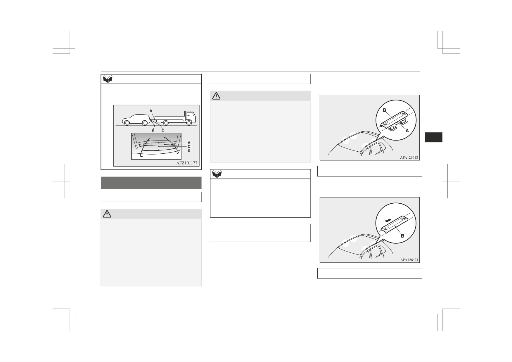
Reference lines on the screen
pear to be closer or further away than they
actually are.
Reference lines and upper surface of the rear
bumper (A) are displayed on the screen.
Starting and driving
6-83

Rear-view camera*
z
Red line
(B) indicates approximately
NOTE
NOTE
50 cm behind the rear bumper.
z
When the vehicle is tilting because of the
• When there is an upward slope at the
z
Two Green lines (C) indicate approxi-
number of people in the vehicle, the weight
back.
mately
20 cm outside of the vehicle
and positioning of luggage, and/or the condi-
body.
tion of the road surface, the lines in the view
z
Short transverse lines (1 to 3) indicate
from the rear-view camera may not be accu-
distance from the rear bumper.
rately positioned relative to the actual road.
The reference lines for distance and vehicle
width are based on a level, flat road surface.
In the following cases, objects shown on the
6
screen will appear to be farther off than they
actually are.
• When the rear of the vehicle is weighed
down with the weight of passengers and
luggage in the vehicle.
Check surroundings for safety.
A- Actual objects
B- Objects shown on the screen
z
The reference lines for distance and vehicle
width are intended to indicate the distance to
a flat object such as a level, flat road surface.
1. Approximately at the rear edge of the
This may make the distance to a projecting
rear bumper (if so equipped)
object shown on the screen differ from the
2. Approximately 100 cm
actual distance to the projecting object. Do
3. Approximately 200 cm
not use them as a guide for distances to solid
objects.
Example: On the screen the point B appears
NOTE
the nearest, then the point C and A in order
A- Actual objects
of distance. The points A and B actually are
z
On vehicles equipped with the Smartphone-
B- Objects shown on the screen
the same distances from the vehicle, and the
link Display Audio
(SDA) or the Smart-
phone- link Display Audio (SDA) naviga-
tion system, it is possible to change the dis-
play language of the screen. For details,
please refer to the separated owner’s manual.
6-84
Starting and driving
Cargo loads
Loading a roof carrier
The brackets (A) are located under each cov-
NOTE
er (B).
point C is farther off than the points A and
B.
CAUTION
z
Use a roof carrier that properly fits your ve-
hicle. Do not load luggage directly onto the
roof. For installation, refer to the instruction
manual accompanying the roof carrier.
z
When attaching/removing the roof carrier
and loading/removing luggage, do not apply
6
excessive pressure on a single point.
Depending on how and where the force is
applied, this may cause dents on the vehicle
Check surroundings for safety.
roof.
Attaching the roof carrier
NOTE
Slide each cover (B) towards the front of the
Cargo loads
We recommend you to use a genuine
z
vehicle to remove it.
MITSUBISHI roof carrier, since the brack-
ets to be used have a special shape.
Cargo loads precautions
For details, we recommend you to consult a
MITSUBISHI MOTORS Authorized Serv-
ice Point.
CAUTION
z Do not load cargo or luggage higher than the
top of the seatback. Be sure that your cargo
Roof carrier mounting brack-
or luggage cannot move once your vehicle is
ets*
moving. Having the driver’s vision blocked,
and your cargo being thrown inside the cabin
Type 1
if you suddenly have to brake can cause a
When installing the roof carrier, use the
serious accident or injury.
brackets (A).
z Load heavy cargo or luggage in the front of
the vehicle. If the load in the back of the ve-
Refitting the covers
hicle is too heavy, steering may become un-
stable.
1. With each cover, put the tabs (C) on the
cover in the holes (D) in the roof.
Starting and driving
6-85

Trailer towing
2. Slide the cover (B) towards the rear of
Roof carrier precautions
NOTE
the vehicle to install it.
z
To prevent wind noise or reduction in fuel
economy, remove the roof carrier when not
CAUTION
in use.
z
Make sure that the weight of the luggage
z Remove the roof carrier before using an au-
does not exceed the allowable roof load.
tomatic car wash.
If the allowable roof load is exceeded, this
z Be sure that adequate clearance is main-
may cause damage to the vehicle.
tained for raising the tailgate when installing
The roof load is the total allowable load on
a roof carrier.
the roof (the weight of the roof carrier plus
6
the weight of luggage placed on the roof car-
rier).
Trailer towing
For the specific value, refer to “Maximum
roof load” on page 11-06.
In order to tow a trailer with your vehicle,
z
When luggage is loaded onto the vehicle,
have a trailer towing device mounted that
please make sure to drive slowly and avoid
meets all relevant regulations in your area,
Type 2
excessive manoeuvres such as sudden brak-
ing or quick turning.
consult a MITSUBISHI MOTORS Author-
When installing the roof carrier, use the
In addition, place the luggage on the carrier
ized Service Point.
brackets (A).
so that its weight is distributed evenly with
The regulations concerning the towing of a
The brackets (A) are located under each roof
the heaviest items on the bottom. Do not
trailer may differ from country to country.
drip moulding (B).
load items that are wider than the roof carri-
You are advised to obey the regulations in
er.
each area.
The additional weight on the roof could raise
the vehicle’s centre of gravity and affect ve-
hicle handling characteristics.
CAUTION
As a result, driving errors or emergency ma-
noeuvres could lead to a loss of control and
z Danger of Accident!
A towing bar should be fitted according to
result in an accident.
Before driving and after travelling a short
MITSUBISHI MOTORS guidelines.
z
distance, always check the load to make sure
it is securely fastened to the roof carrier.
Check periodically during your travel that
the load remains secure.
6-86
Starting and driving

Trailer towing
Maximum towable weight with
Towing bar mounting specifica-
brake and maximum trailer-
tions
nose weight
See the following table for fixing points (A)
Never exceed the maximum towable weight
for the towing bar.
with brake and the maximum trailer-nose
weight as listed in the specifications.
(Refer to page 11-06.)
If you tow a trailer at an altitude of more than
1,000 m above sea-level, reduce your weight
6
by 10 % of the gross combination weight for
every increase of 1,000 m above sea-level, as
the engine output is lowered owing to de-
crease in atmospheric pressure.
1
838.5 mm
2
461 mm
3
68.5 mm
4
77 mm
5
310 mm
6
13.5 mm
7
66.5 mm
8
50 mm
9
48 mm
468 mm to 480 mm
10
(at kerb weight con-
dition)
Starting and driving
6-87
Trailer towing
382 mm to 398 mm
Additional precautions for vehi-
CAUTION
(at laden condition)
cles equipped with a CVT
z
On vehicles equipped with CVT, if the
11
447 mm
It is recommended the “D” position on slopes
warning display is showing, the temperature
or at low speed.
of the CVT fluid is high.
12
487 mm
Use the sports mode in mountainous areas in
Read the reference page and take the re-
13
495 mm
order to make better use of engine braking
quired measures.
Refer to “When a malfunction occurs in the
and to assist the brake system. However, be
14
525.5 mm
CVT” on page 6-28.
sure that the speed does not exceed the maxi-
mum speed limit for the selected shift posi-
6
NOTE
tion.
z The values under item 12 can be varied de-
Overheating
pending on the loading condition of cargo or
luggage.
This will normally occur as a result of some
mechanical failure. If your vehicle should
Operating hints
overheat, stop and check for a loose or bro-
ken water pump/alternator drive belt, a
z To prevent the clutch from slipping (Ve-
blocked radiator air intake or a low coolant
hicle with a M/T only), do not rev the
level. If these items are satisfactory the over-
engine more than is required when start-
heating could be caused by a number of me-
ing off.
chanical causes that would have to be
z Be sure that the driving speed does not
checked at a competent service centre.
exceed 100 km/h (62 mph) for trailer op-
eration. It is also recommended that you
CAUTION
obey the local regulations in case driving
speed with a trailer is limited to less than
z If the engine overheats, please refer to the
100 km/h (62 mph).
“Engine overheating” section of “For emer-
gencies” prior to taking any corrective ac-
z To prevent shocks from the overrun
tion.
brake, depress the brake pedal lightly at
first and then more strongly.
z To make full use of engine braking,
change to a lower shift point before de-
scending a slope.
6-88
Starting and driving
For pleasant driving
Ventilators
7-02
Accessory socket*
7-71
Air conditioning
7-03
Interior lamps
7-71
Important operation tips for the air conditioning
7-10
Storage spaces
7-75
Air purifier
7-11
Cup holder
7-78
LW/MW/FM radio/CD player*
7-11
Bottle holder
7-78
Handling of Discs
7-14
Rear shelf panel*
7-79
7
Audio Files (MP3/WMA/AAC)
7-15
Assist grips
7-79
Important Points on Safety for the Customer
7-19
Coat hook
7-80
Operation Keys
7-20
Luggage hooks
7-80
Listen to Radio
7-23
Listen to DAB*
7-24
Listen to Traffic Messages
7-26
Listen to CDs
7-26
Listen to MP3s
7-27
Listening to an iPod
7-28
Listen to Audio Files on a USB Device
7-30
To play iPod/USB memory device tracks via voice opera-
tion (vehicles with Bluetooth® 2.0 interface)
7-32
Listening to Bluetooth® Audio*
7-35
Display Indicator
7-38
Audio Quality and Volume Balance Adjustment
7-39
System settings
7-40
Troubleshooting
7-44
Link System*
7-46
Bluetooth® 2.0 interface*
7-46
USB input terminal*
7-66
Sun visors
7-68
Ashtray*
7-69
Cigarette lighter*
7-70

Ventilators
To close the ventilator, fully move the knob
To close the ventilator, fully move the knob
Ventilators
(A) to the inner side.
(A) to the outer side.
Type 1
Left
Right
7
1- Close
1- Centre ventilators
2- Open
2- Side ventilators
Type 2
NOTE
NOTE
z The cool air from the ventilators may appear
as a mist.
z Do not place beverages on top of the instru-
This is due to moist air being suddenly
ment panel.
cooled by the air conditioning. This will
If they splash into the air conditioning venti-
clear after a few moments.
lators, they could damage the system.
z Be careful not to spill drinks, etc., into the
ventilators.
Air flow and direction adjust-
Doing so might cause the air conditioning
not to function normally.
ments
1- Close
2- Open
Centre ventilators
Side ventilators
Move the knob (A) to adjust the air flow di-
Move the knob (A) to adjust the air flow di-
rection.
rection.
7-02
For pleasant driving
Air conditioning
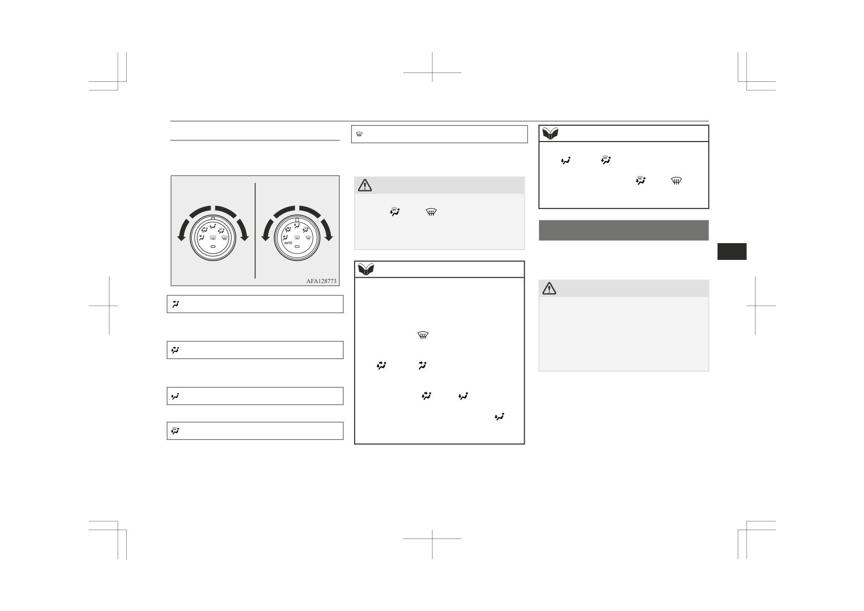
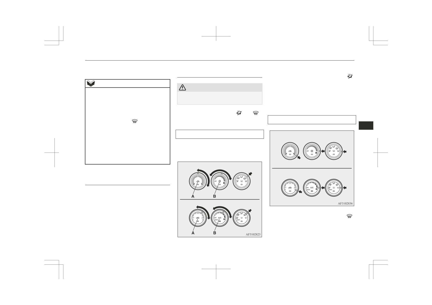
Mode selection dial
Demister position
NOTE
To change the amount of air flowing from the
Air flows mainly to the windscreen and the
z With the mode selection dial between the
ventilators, turn the mode selection dial.
door windows.
“
” and
“
” positions, the air flows
mainly to the leg area. With the mode selec-
Manual air
Automatic air
tion dial between the “
” and “
” posi-
CAUTION
conditioning
conditioning
tions, the air flows mainly to the windscreen
z
When using the mode selection dial between
and door windows.
the “
” and “
” positions, prevent fog-
ging by pressing the air selection switch to
select outside air.
(Refer to “Air selection
Air conditioning
switch” on page 7-05.)
The air conditioning can only be used while
7
the engine is running.
NOTE
z
For vehicles equipped with the Auto Stop &
CAUTION
Go (AS&G) system, the windscreen and
Face position
door windows may mist up while the AS&G
z The engine speed may increase when the air
system is operating. If the windscreen and
conditioning is operating.
Air flows only to the upper part of the pas-
door windows mist up, set the mode selec-
With an increased engine speed, a CVT ve-
senger compartment.
tion dial to “
” to demist the windscreen
hicle will creep to a greater degree than with
and door windows.
a lower engine speed. Fully depress the
Foot/face position
With the mode selection dial between the
brake pedal to prevent the vehicle from
z
Air flows to the upper part of the passenger
“
” and
“
” positions, the air flows
creeping.
compartment, and flows to the leg area.
mainly to the upper part of the passenger
compartment. With the mode selection dial
Foot position
between the “
” and “
” positions, the
air flows mainly to the leg area.
Air flows mainly to the leg area.
z
With the mode selection dial in the “
” po-
sition, a small amount of air flows to the
Foot/demister position
windscreen and the door windows.
Air flows to the leg area, the windscreen and
the door windows.
For pleasant driving
7-03

Air conditioning
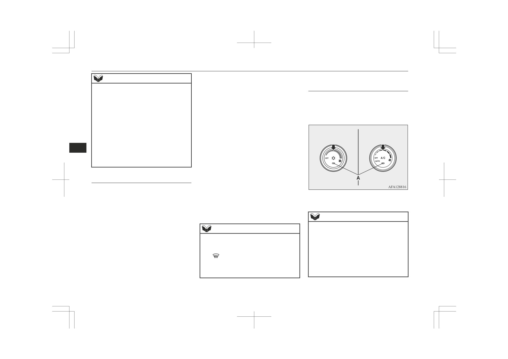
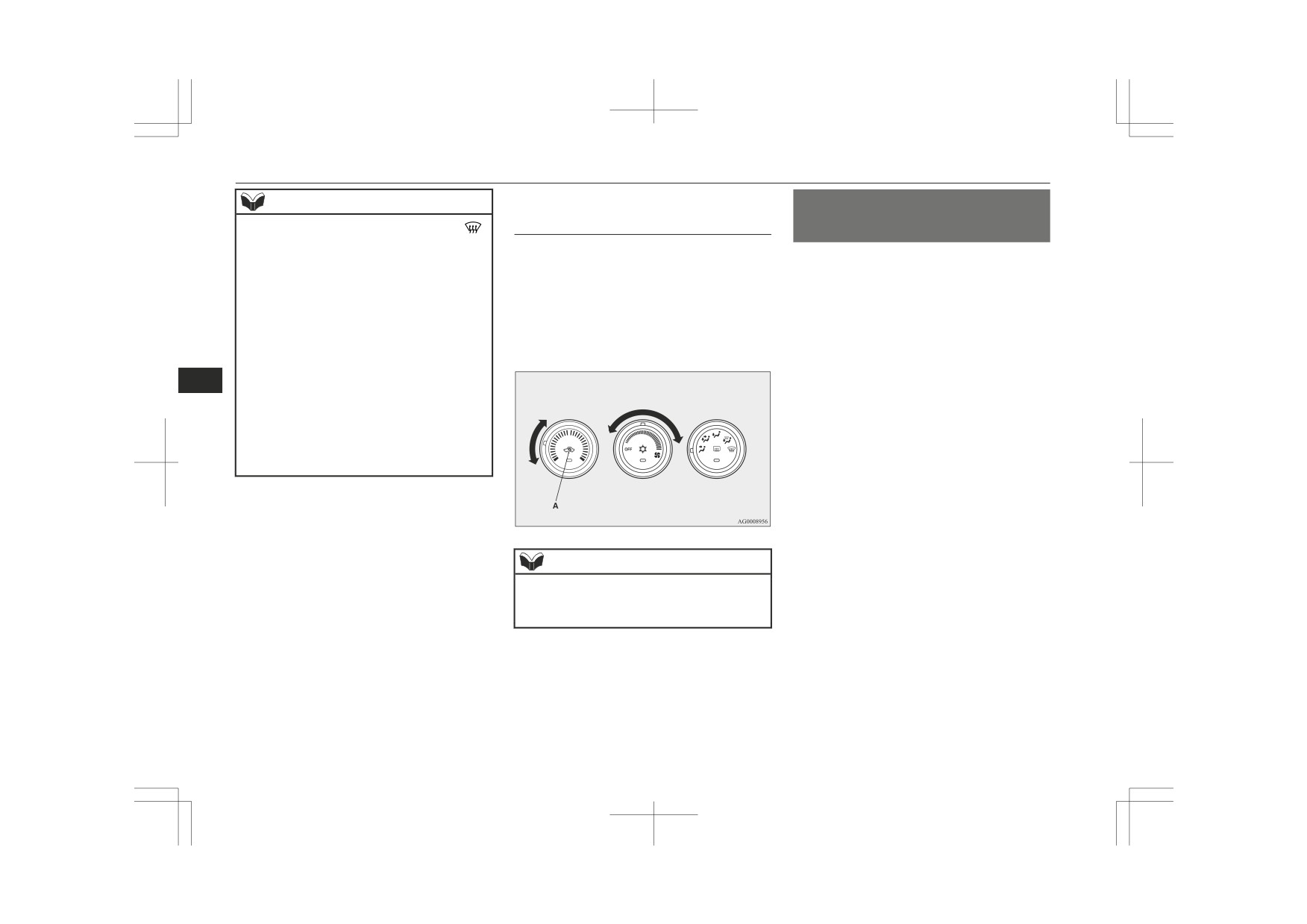
Control panel
Turn the dial clockwise to increase the air
NOTE
flow and anticlockwise to decrease the air
z
On vehicles with automatic air conditioning,
flow.
Manual air conditioning
there is an interior air temperature sensor
(G) in the illustrated position.
Never place anything over the sensor, since
Manual air
Automatic air
doing so will prevent it from functioning
conditioning
conditioning
properly.
Automatic air conditioning
7
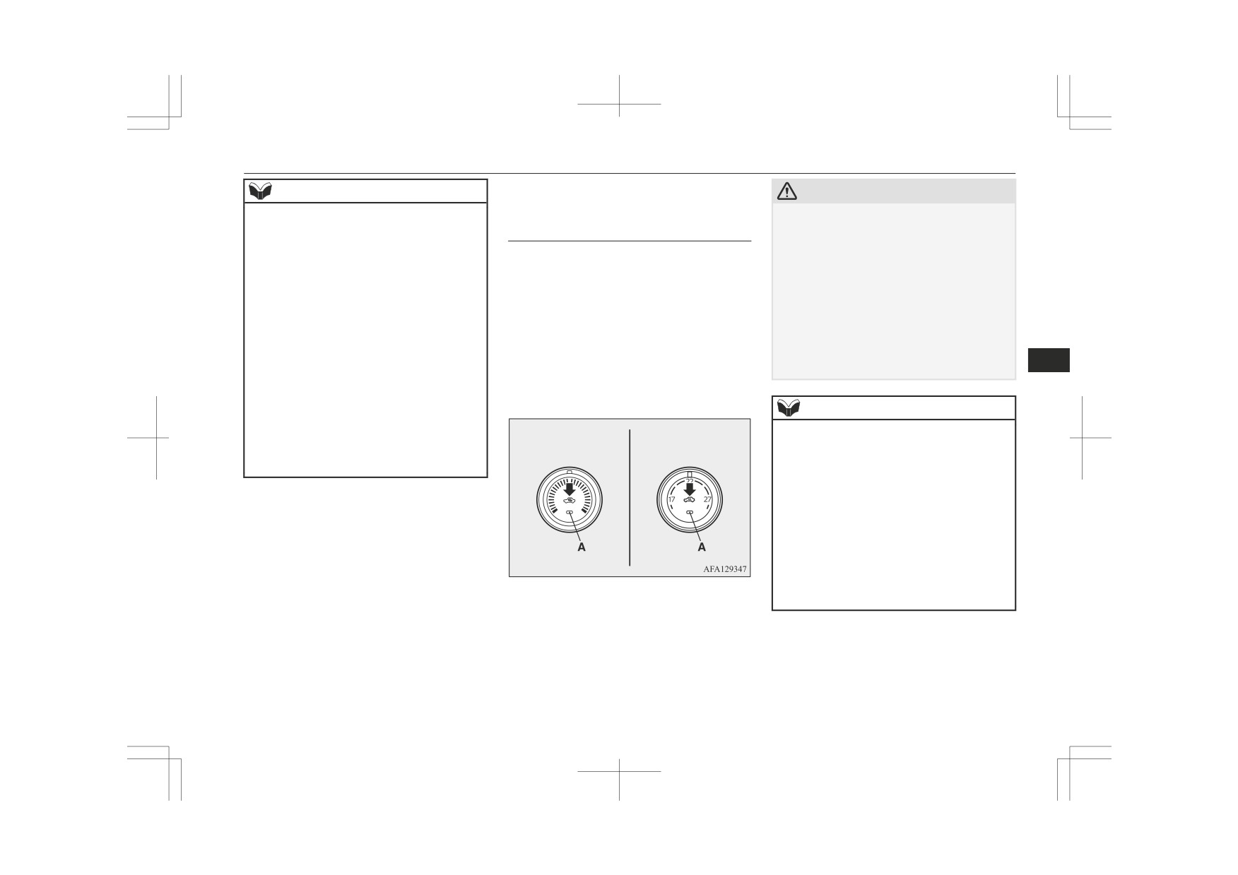
Temperature control dial
Turn the temperature control dial clockwise
A- Temperature control dial
Blower speed selection dial
or anticlockwise.
B- Air selection switch
Select the blower speed by turning the blower
C- Blower speed selection dial
speed selection dial clockwise or anticlock-
Manual air
Automatic air
D- Air conditioning switch
wise.
conditioning
conditioning
E- Mode selection dial
F- Rear window demister switch ® p. 5-62
7-04
For pleasant driving
Air conditioning
Refer to “Customizing the air selection” on
NOTE
CAUTION
page 7-06.
z While the engine coolant temperature is low,
z
Normally, use the outside position to keep
the temperature of the air from the heater
Air selection switch
the windscreen and side windows clear and
will be cool/cold until the engine warms up,
quickly remove fog or frost from the wind-
To change the air selection, simply press the
even if you have selected warm air with the
screen.
air selection switch. There is a sound each
dial.
If high cooling performance is desired, or if
time the switch is pressed.
the outside air is dusty or otherwise contami-
z On vehicles with the automatic air condi-
tioning, when the temperature is set to the
z Outside air: Indication lamp (A) is OFF
nated use the recirculation position. Switch
highest or the lowest setting under the AU-
Outside air is introduced into the passen-
to the outside position periodically to in-
TO operation, the air selection and the air
ger compartment.
crease ventilation so that the windows do not
conditioning will be automatically changed
become fogged up.
z Recirculated air: Indication lamp (A) is
as follows.
z
Use of the recirculation position for exten-
ON
7
• Quick Heating (When the temperature is
ded time may cause the windows to fog up.
Air is recirculated inside the passenger
set to the highest setting)
compartment.
Outside air will be introduced and the air
conditioning will stop.
NOTE
• Quick Cooling (When the temperature is
Manual air
Automatic air
z
On vehicles with the manual air condition-
set to the lowest setting)
conditioning
conditioning
ing, when the system operates with the se-
Inside air will be recirculated and the air
lection switch in the outside position, the
conditioning will operate.
system automatically determines whether to
continue using outside air or to perform re-
The settings described above are the factory
circulation. If the outside air temperature is
settings. The air selection and air condition-
high, the system selects recirculation and
causes the indication lamp (A) in the switch
ing switches can be customized (function set-
to illuminate (for vehicles with the manual
ting changed), and the automatic switching of
air conditioning, the system selects recircu-
outside air and the air conditioner according
lation to achieve rapid cooling). Press the se-
to operating conditions can be changed as de-
lection switch to return to outside air intro-
sired.
duction.
For further information, we recommend you
to consult a MITSUBISHI MOTORS Au-
thorized Service Point.
Refer to “Customizing the air conditioning
switch (Automatic air conditioning)” on page
7-07.
For pleasant driving
7-05
Air conditioning
• Manual air conditioning:
NOTE
Air conditioning switch (Air
Even when the system operates, the
conditioning)
z On vehicles with the automatic air condi-
air selection switch will not be auto-
tioning, when the mode selection dial or the
Push the switch to turn the air conditioning
matically controlled.
blower speed selection dial is set to the
on, indication lamp (A) will come on.
• Automatic air conditioning:
“AUTO” position again after manual opera-
There is a sound each time the switch is
tion, the air selection dial will also be auto-
Even when the mode selection dial or
pressed.
matically controlled.
blower speed selection dial is turned
z On vehicles with the automatic air condi-
to the “AUTO” position, the air selec-
tioning, when the engine coolant tempera-
tion switch is not controlled automati-
Manual air
Automatic air
ture rises to a certain level, the air selection
cally.
conditioning
conditioning
is automatically switched to the recirculation
z
Setting change method
position and the indication lamp (A) comes
7
Hold down the air selection switch for
on. At this time, the system will not switch
to the outside position even if the air selec-
about 10 seconds or more.
tion switch is pushed.
When the setting is changed, a sound is
emitted and the indication lamp flashes.
• When the setting is changed from ena-
Customizing the air selection
ble to disable 3 sounds are emitted and
Functions can be changed as desired, as sta-
the indication lamp flashes 3 times.
ted below.
• When the setting is changed from dis-
z Enable automatic air control
able to enable 2 sounds are emitted
Push the switch again to switch it off.
• Manual air conditioning:
and the indication lamp flashes
3
When the system operates, the air se-
times.
lection switch will be automatically
NOTE
controlled.
z If a problem is detected in the air condition-
NOTE
• Automatic air conditioning:
ing system, the air conditioning operation in-
The factory setting is “Enable automatic air
dication lamp (A) blinks. Press the air condi-
When the mode selection dial or
z
blower speed selection dial is turned
control”.
tioning switch once to turn it off, then once
When the mode selection dial is turned to
more to turn it back on. If the air condition-
to the “AUTO” position, the air selec-
z
“
”, in order to prevent misting of the
ing operation indication lamp does not blink
tion switch is also controlled automat-
windows the ventilator automatically
for a while, there is nothing wrong. If it
ically.
switches to outside air even if “Disable auto-
starts to blink again, we recommend you to
z Disable automatic air control
have it checked.
matic air control” is set.
7-06
For pleasant driving

Air conditioning
When the setting is changed, a sound is
Turn the temperature control dial clockwise
NOTE
emitted and the indication lamp flashes.
or anticlockwise to the desired temperature.
z Sometimes, for example after using a high-
• When the setting is changed from ena-
Select the desired blower speed.
pressure car wash, the condenser can get
ble to disable 3 sounds are emitted and
wet, and the operation indication lamp (A)
the indication lamp flashes 3 times.
blinks temporarily. In this case there is noth-
ing wrong. Wait a while, press the air condi-
• When the setting is changed from dis-
tioning switch once to turn the system off,
able to enable 2 sounds are emitted
then once more to turn it back on. Once the
and the indication lamp flashes
3
water evaporates, the blinking will stop.
times.
Customizing the air condition-
NOTE
7
ing switch (Automatic air condi-
z The factory setting is “Enable automatic air
conditioning control”.
tioning)
z When you turn the mode selection dial to
Functions can be changed as desired, as sta-
“
”, in order to prevent misting of the
ted below.
NOTE
windows the air conditioning operates auto-
z Enable automatic air conditioning con-
matically even if “Disable automatic air con-
For quick heating, set the blower speed se-
z
trol:
ditioning control” is set.
lection dial to the position shown in the il-
If the mode selection dial or blower
lustration.
speed selection dial is turned to the
Operating the air conditioning
“AUTO” position, or the temperature
system
control dial is set to the minimum tem-
perature, the air conditioning switch is
controlled automatically.
Heating (Manual air condition-
ing)
z Disable automatic air conditioning con-
trol:
Set the mode selection dial to the “
” posi-
The air conditioning switch is not con-
tion and set the air selection switch (A) to the
trolled automatically as long as the air
outside position.
conditioning switch is not operated.
z Setting change method
Hold down the air conditioning switch
for about 10 seconds or more.
For pleasant driving
7-07

Air conditioning
Warm air flows to the leg area and unheated
Cooling (Manual air condition-
NOTE
or slightly warm air (depending upon temper-
ing)
z When the air conditioning operates with the
ature setting) flows to the upper part of the
selection switch in the outside position, the
passenger compartment.
system automatically determines whether to
continue using outside air or to perform re-
Automatic mode (Automatic air
circulation. If the outside air temperature is
high, the system selects recirculation to ach-
conditioning)
ieve rapid cooling and causes the indication
lamp in the switch to illuminate. Press the
selection switch to return to outside air intro-
duction.
7
Combination of unheated air
1. Set the mode selection dial to the “
”
and heated air (Manual air con-
position.
ditioning)
2. Set the air selection switch (A) to the
Select the mode selection dial to the position
outside position.
shown in the illustration and set the air selec-
3. Push the air conditioning switch (B).
tion switch (A) to the outside position.
4. Change the temperature by turning the
The air flow will be directed to the leg area
control dial clockwise or anticlockwise.
and the upper part of the passenger compart-
In normal conditions, use the system in the
5. Select the desired blower speed.
ment. Select the desired blower speed.
AUTO mode and follow these procedures:
1. Set the blower speed selection dial to the
CAUTION
“AUTO” position.
2. Set the temperature control dial to the
z
If the outside air is dusty or otherwise conta-
desired temperature.
minated, or if high cooling performance is
desired, set air selection switch to the recir-
3. Set the mode selection dial to the “AU-
culation position and the temperature control
TO” position.
dial all the way to the left.
Switch to the outside position periodically to
The outlet position recirculation/outside air
increase ventilation so that the windows do
select and blower speed, and ON/OFF of the
not become fogged up.
air conditioning will be controlled automati-
cally.
7-08
For pleasant driving
Air conditioning
To stop the system, turn the blower speed se-
1. Set the air selection switch (A) to the
Demisting of the windscreen
lection dial to the “OFF” position.
outside position.
and door windows
2. Set the mode selection dial to the “
”
position.
NOTE
CAUTION
3. Select your desired blower speed by
z While the engine coolant temperature is low,
turning the blower speed selection dial.
the temperature of the air from the heater
z For safety, make sure you have a clear view
4. Select your desired temperature by turn-
will be cool/cold until the engine warms up,
through all the windows.
ing the temperature control dial.
even if you have selected warm air with the
5. Push the air conditioning switch (B).
dial. To prevent the windscreen and win-
Use the mode selection dial (“
” or “
”)
dows from fogging up, the ventilator mode
to remove frost or mist from the windscreen
For quick demisting
will be changed to “
” and the blower
or door windows.
speed will be reduced.
7
z If the blower speed selection dial, air condi-
For ordinary demisting
Manual air conditioning
tioning switch, mode selection dial, or air se-
lection switch is operated while the system
Perform the following settings to prevent
is operating in the AUTO mode, the activa-
misting of the windscreen and door windows,
ted function overrides the corresponding
and to heat the leg area.
function of automatic control. All other
functions remain under automatic control.
Manual air conditioning
Automatic air conditioning
Manual mode (Automatic air
conditioning)
Blower speed and ventilator mode may be
controlled manually by setting the blower
speed selection dial and the mode selection
Automatic air conditioning
dial to the desired positions. To return to au-
tomatic operation, set the dials to the “AU-
TO” position.
1. Set the mode selection dial to the “
”
position.
2. Set the blower to the maximum speed.
3. Set the temperature to the highest posi-
tion.
For pleasant driving
7-09
Important operation tips for the air conditioning
NOTE
Introduction of outside air
Important operation tips for
z
When the mode selection dial is in the “
”
(Manual air conditioning)
the air conditioning
position, the system operates automatically
To introduce air into the vehicle during hot
and outside air is set automatically.
weather, set the air selection switch (A) to the
z
Park the vehicle in the shade.
z
To demist effectively, direct the air flow
outside position and set the temperature con-
Parking in the hot sun will make the ve-
from the side ventilators towards the door
trol dial to the positions shown in the illustra-
hicle inside extremely hot, and it will re-
windows.
tion. Be sure to set the temperature control
quire more time to cool the interior.
z
Do not set the temperature control dial to the
dial all the way to the left. Select the desired
If it is necessary to park in the sun, open
max. cool position. Cool air will blow
against the window glasses and prevent de-
blower speed.
the windows for the first few minutes of
misting.
air conditioning operation to expel the
z
For vehicles with the Auto Stop & Go
hot air.
7
(AS&G) system, if the mode selection dial is
z
Close the windows when the air condi-
set to the demister position shown in the il-
tioning is in use. The entry of outside air
lustration, the AS&G system will not oper-
through open windows will reduce the
ate and the engine will not stop automatical-
cooling efficiency.
ly even if the vehicle is stopped. This is to
ensure that good visibility is maintained.
z
Too much cooling is not good for the
health. Keep the difference between the
vehicle interior temperature and outside
temperature at 5 to 6 °C.
z
When operating the system, make sure
the air intake, which is located in front
NOTE
of the windscreen, is free of obstructions
such as leaves and snow. Leaves collec-
z Turn the mode selection dial clockwise and
ted in the air-intake plenum may reduce
air will flow to the leg area and the wind-
air flow and plug the plenum water
screen.
drains.
7-10
For pleasant driving

Air purifier
Air conditioning system refrig-
Air purifier
NOTE
erant and lubricant recommen-
z
To listen to the audio system while the en-
An air filter has been incorporated into the air
dations
gine is not running, turn the ignition switch
conditioning so that pollen and dust are
to the “ACC” position or put the operation
If the air conditioning seems less effective
cleaned from the air.
mode in ACC.
than usual, the cause might be a refrigerant
Replace the air filter periodically as its ability
If the ignition switch or the operation mode
is left in ACC, the accessory power will au-
leak. We recommend you to have the system
to clean the air will be reduced as it collects
tomatically turn off after a certain period of
inspected.
pollen and dirt. For the maintenance interval,
time and you will no longer be able to use
The air conditioning system in your vehicle
refer to the “SERVICE BOOKLET”.
the audio system. The accessory power
must be charged with the refrigerant
comes on again if the ignition switch or the
HFO-1234yf (Except for vehicles for Moldo-
engine switch is operated with it in the
NOTE
7
va and Ukraine) or HFC-134a (Vehicles for
“ACC” position. Refer to “ACC power auto-
Moldova and Ukraine) and the lubricant
z Operation in certain conditions such as driv-
cutout function” on pages 3-15 and 6-12.
ing on a dusty road and frequent use of the
If a cellular phone is used inside the vehicle,
PAG46A (Except for vehicles for Moldova
z
air conditioning can lead to reduction of
it may create noise from the audio equip-
and Ukraine) or SUN-PAG56 (Vehicles for
service life of the filter. When you feel that
ment. This does not mean that anything is
Moldova and Ukraine).
the air flow is lower than normal or when
wrong with your audio equipment. In such a
Use of any other refrigerant or lubricant will
the windscreen or windows start to fog up
case, use the cellular phone at a place as far
cause severe damage which will result in the
easily, replace the air filter.
away as possible from the audio equipment.
need to replace your vehicle’s entire air con-
We recommend you to have it checked.
If foreign objects or water get into the audio
z
ditioning system. The release of refrigerant
equipment, or if smoke or a strange odour
comes from it, immediately turn off the au-
into the atmosphere is not recommended.
LW/MW/FM radio/CD
dio system. We recommend you to have it
We recommend you to recover and recycle
checked. Never try to repair it by yourself.
the refrigerant for reuse.
player*
Avoid continuous usage without inspection
by a qualified person.
During a long period of disuse
The audio system can only be used when the
ignition switch or the operation mode is in
The air conditioning should be operated for at
ON or ACC.
least five minutes each week, even in cold
weather. This is to prevent the compressor
from seizing and to maintain the air condi-
tioning in the best operating condition.
For pleasant driving
7-11

LW/MW/FM radio/CD player*
Important Points on Usage
z
Furthermore, even if there is no specific
NOTE
denotation of trademarks or registered
z
For vehicles with a Bluetooth® 2.0 interface,
trademarks, these are to be observed in
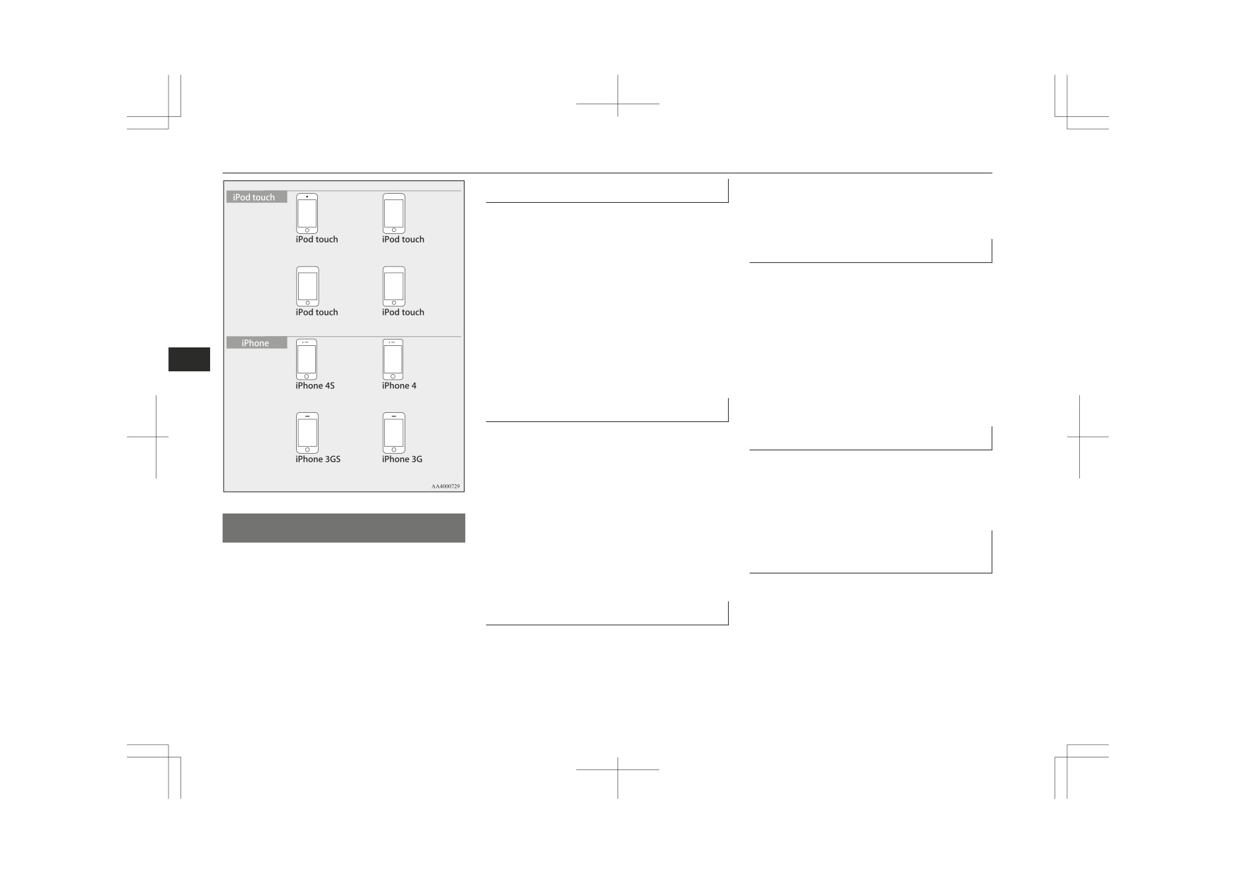
iPod/iPhone Playback Func-
the types of devices that can be connected
their entirety.
tion*
may vary. For details, access the
MITSUBISHI MOTORS website.
z This product supports audio playback
Please read and agree to the “Warning about
from iPod/iPhone devices, however dif-
Links to the Web Sites of Other Compa-
fering versions mean that playback can-
nies”.
not be guaranteed.
The websites mentioned above may connect
z Please be aware that depending on the
you to websites other than the MITSUBISHI
iPod/iPhone model or version, operation
MOTORS website.
7
may differ.
“Made for iPod,”
“Made for iPhone”
ucts/index.html
mean that an electronic accessory has
Bluetooth® is a registered trademark of
How to Clean
been designed to connect specifically to
BLUETOOTH SIG, INC.
iPod or iPhone, respectively, and has
z If the product becomes dirty, wipe with a
been certified by the developer to meet
soft cloth.
Apple performance standards.
z If very dirty, use a soft cloth dipped in
iPhone, iPod, iPod classic, iPod nano,
neutral detergent diluted in water, and
and iPod touch are trademarks of Apple
then wrung out. Do not use benzene,
Inc., registered in the U.S. and other
thinners, or other chemical wipes. This
countries.
may harm the surface.
Apple is not responsible for the opera-
tion of this device or its compliance with
Trademarks
safety and regulatory standards.
z Product names and other proper names
are the trademarks or registered trade-
NOTE
marks of their respective owners.
z
iPod and iTunes licensing allows individual
users to privately reproduce and play back
non- copyrighted material as well as material
that may be legally copied and reproduced.
Infringement of copyright is prohibited.
7-12
For pleasant driving

LW/MW/FM radio/CD player*
5th generation
5th generation
(video)
(video)
7
6th generation
5th generation
4th generation (video)
(video camera)
3rd generation
2nd generation
1st generation
(video)
(aluminium)
For pleasant driving
7-13
Handling of Discs
Important Points on Handling
z If discs are not going to be used for a
long period of time, remove these from
z Fingerprints or other marks on the read
the product.
surface of the disc may result in its con-
4th generation
3rd generation
tent being more difficult to read. When
Disc Playback Environment
8GB 32GB 64GB
32GB 64GB
holding the disc, grip both edges, or one
edge and the centre hole, in order that
In cold environments such as in mid-winter
the read surface is not touched.
when the interior of the vehicle is cold, turn-
ing the heater on and immediately trying to
z Do not affix paper or stickers, or other-
2nd generation
1st generation
use the product may cause condensation (wa-
8GB 16GB 32GB
8GB 16GB 32GB
wise damage the disc.
ter droplets) to form on the disc and internal
z Do not forcefully insert a disc if another
7
is already within the device. This can re-
optical components, and this may prevent the
sult in damage to discs, or malfunction.
product from operating correctly.
In these conditions, remove the disc, and wait
16GB 32GB 64GB
16GB 32GB
Cleaning
a short time before use.
z Periodically clean the read surface of the
Copyright
disc. When cleaning, do not wipe in a
8GB 16GB 32GB
8GB 16GB
circular motion. Instead, wipe gently
Actions such as unauthorized reproduction,
broadcast, public performance, or rental of
outwards from the centre of the disc to
the outer edge.
discs that comprise other than personal use
are prohibited by law.
z New discs may have burring around the
Handling of Discs
outer edge or in the hole in the centre.
Types of Disc That Can Be
Ensure you check for these. If there are
This explains care that should be taken in the
Played Back
burrs, these may lead to faulty operation,
handling of discs.
therefore ensure these are removed.
The following marks are printed on the disc
label, package, or jacket.
Important Points on Storage
z When not using discs, ensure these are
kept in cases, and stored out of direct
sunlight.
7-14
For pleasant driving

Audio Files (MP3/WMA/AAC)
Maxi-
z
Do not insert irregularly-shaped discs
z Playback of other than standard CDs is
mum
(for example, heartshaped), as these may
not guaranteed. Even if the audio can be
Type
Size
play-
Comments
result in malfunction. Additionally, discs
played back, the audio quality cannot be
that have transparent portions may not
guaranteed.
back
time
be played back.
z When playing back other than standard
z
Discs that have not been finalized cannot
CDs, the following may occur.
CD-DA
12 cm
74 mi-
—
be played back.
• There may be noise during playback.
nutes
z
Even if recorded using the correct for-
• There may be jumping in the audio.
mat on a recorder or computer, applica-
• The disc may not be recognized.
tion software settings and environments;
• The first track may not be played
CD-
12 cm
74 mi-
—
disc peculiarities, damage, or marking;
back.
TEXT
nutes
or dirt or condensation on the lens inside
• It may take longer than usual until
7
the product may render the disc unplaya-
start of playback of tracks.
ble.
• Playback may start from within the
z
Depending on the disc, some functions
track.
CD-
12 cm
—
•Disc contain-
may not be used, or the disc may not
• Some parts may not be played back.
R/RW
ing MP3 files
play back.
• Tracks may freeze during playback.
z
Do not use discs with cracks or warps.
• Tracks may be displayed erroneously.
z
If the disc has stickers affixed, remains
from removed stickers, or affixed adhe-
Audio Files (MP3/WMA/
sive, then do not use the disc.
AAC)
z
Discs that have decorative labels or
stickers may not be used.
This product can play back MP3/WMA/AAC
Discs That May Not Be Played
Nonstandard CDs
format audio files recorded on CD-ROM,
Back
CD-R/RW, and USB devices.
This product will play back audio CDs, how-
z Playback of discs other than those de-
ever please be aware of the following points
scribed in “Types of Disc That Can Be
regarding CD standards.
Played Back” is not guaranteed.
z Ensure that you use discs with
on
z
8 cm discs may not be used.
the label surface.
For pleasant driving
7-15