Mitsubishi ASX (2020 year). Manual in english - page 11
Radar sensing misacceleration Mitigation System (RMS) (Forward)*
CAUTION
z
The RMS (Forward) may not operate because the sensor cannot detect the front vehicle or obstacle as follows.
• Obstacles that infrared rays are permeabilised, such as a fence with large mesh, glass etc.
• Obstacles that have the shape of the pole such as the road marker or the streetlight.
• Obstacles that are not vertical to the ground.
• Obstacles that are not at right angles to vehicle traveling direction.
• A wall surface that is not flat.
• Vehicles or obstacles with the low height.
• Vehicles or obstacles that are extremely stained.
6
• Vehicles or obstacles that have a dark colour.
• Vehicle or obstacle that is covered with snow.
• Vehicle towing a trailer etc.
• A freight trailer that is not carrying a container.
• Vehicle that has a protruding load from the carrier.
• Vehicle that has an extremely high ground clearance.
• Vehicles that have a large glass surface.
• Vehicles that do not have reflectors (lamp reflector) or the position of the reflector is low.
• Vehicles that have a specific shape such as the carrier car.
z
The RMS (Forward) may be triggered operate in the following situations.
• When there is a road side object in a curb or an intersection.
• When your vehicle joins the main line.
• When there are metallic objects, steps or projections on the road surface.
• When an electronic toll collection gate, parking gate or railway barrier is raised imperfectly.
• When starting on an uphill slope.
• When running the road, the gradient changes suddenly.
• When passing through the mass of the steam, fog or smoke.
• When driving close to the vehicle ahead.
• When passing close to a vehicle or an obstacle.
• When passing through a plastic curtain etc.
• When there are long objects such as a skis on a roof carrier in the detective range of the sensor.
6-62
Starting and driving
Blind Spot Warning (BSW) (with Lane Change Assist)*
CAUTION
z Turn off the RMS (Forward) with the FCM and RMS (Forward)* ON/OFF switch beforehand when the vehicle is placed in any of the following situations
as the system can operate unexpectedly.
• When using an automatic car wash.
• When your vehicle’s wheels are driven by the engine on a lift.
• When your vehicle is towed.
• When your vehicle is carried on a truck.
• When enjoying sports driving on a circuit.
• When your vehicle is on a chassis dynamometer or free rollers.
6
• When the tyre pressure is not correct.
• When tyre chains are attached.
To turn on/off the RMS (For-
Blind Spot Warning (BSW)
Depending on the speed of your vehicle, the
BSW system will detect up to approximately
ward)
(with Lane Change Assist)*
70 m from your vehicle.
The RMS (Forward) is automatically turned
ON by setting the ignition switch or the oper-
The Blind Spot Warning (BSW) is a driving
ation mode to ON.
aid system that alerts the driver when another
If you want to turn off a system, refer to
vehicle, which may not be visible through the
“FCM and Radar sensing misacceleration
outside rear-view mirror, is travelling in the
Mitigation System
(RMS)
(Forward)
next lane behind your vehicle.
ON/OFF switch” on page 6-54.
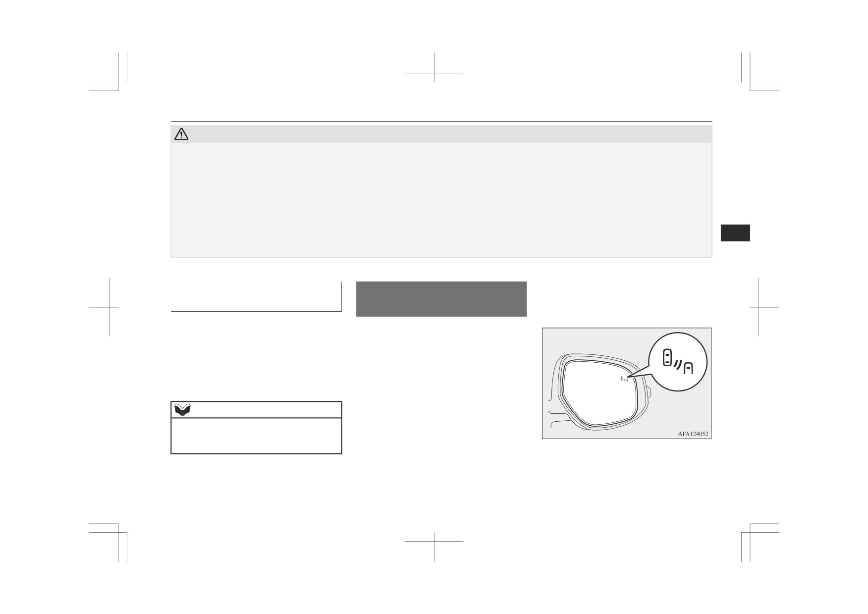
When a vehicle in the next lane is travelling
at the same speed or faster in the detection
areas, the Blind Spot Warning lamp in the
NOTE
corresponding outside rear-view mirror will
z The RMS (Forward) ON/OFF is switched in
illuminate. If the turn-signal lever is operated
conjunction with the ON/OFF state of the
to the side where the Blind Spot Warning
FCM.
lamp is illuminated, the Blind Spot Warning
lamp will blink and the system will beep
three times to alert the driver.
Starting and driving
6-63
Blind Spot Warning (BSW) (with Lane Change Assist)*
WARNING
WARNING
z Before using the BSW, read this entire
• When a vehicle is travelling alongside
section to fully understand the limitations
of your vehicle at nearly the same speed
of this system. Failure to follow instruc-
for prolonged periods of time.
tions could result in an accident.
• When the heights of the next lane and
z Never rely solely on the BSW system
your lane are different.
when changing lanes. The BSW is an aid
• Immediately after the BSW has been
only. It is not a substitute for your safe
turned on.
and careful driving. Always check visually
• Immediately after the ignition switch is
behind and all around your vehicle for
turned to the “ON” position or the op-
6
other vehicles.
eration mode is put in ON.
The performance of the BSW may vary
• Under adverse weather conditions,
depending on driving, traffic and/or road
such as rain, snow, strong winds, snow
conditions.
or sand storms.
• When your vehicle comes too close to
another vehicle.
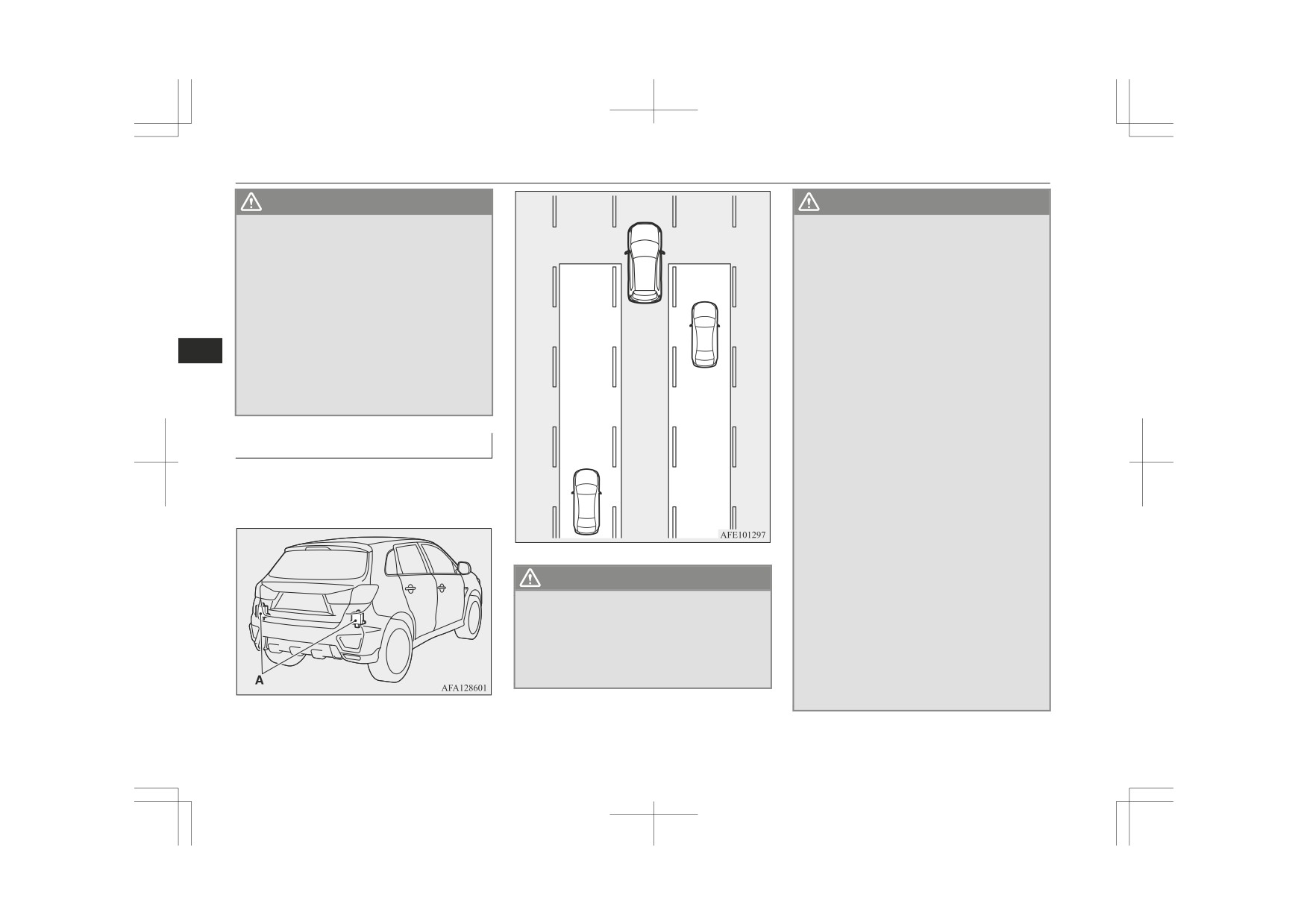
Detection areas
• While multiple vehicles are overtaking
your vehicle.
The BSW uses two sensors (A) located inside
• When driving near a pot hole and
the rear bumper.
tramline.
The detection areas are shown as illustrated.
• When a surrounding vehicle or an on-
coming vehicle is splashing water, snow
or dirt.
• When driving on a curve including the
beginning and the end of the curve.
WARNING
• When driving on a road with alternat-
ing up and down steep slopes.
z
In certain situations, the BSW may not
• When driving on a bumpy or rough
detect a vehicle in the detection areas or
road.
the detection may be delayed. Some of
• When the rear of your vehicle is weigh-
these include:
ed down or your vehicle is leaning to
• When a small motorcycle or a bicycle is
the right or left due to the weight of
behind your vehicle.
passengers and luggage or the improp-
er adjustment of tyre pressure.
6-64
Starting and driving
Blind Spot Warning (BSW) (with Lane Change Assist)*
To operate
If you turn the BSW ON/OFF, the Rear Cross
WARNING
Traffic Alert (RCTA) also turns ON/OFF at
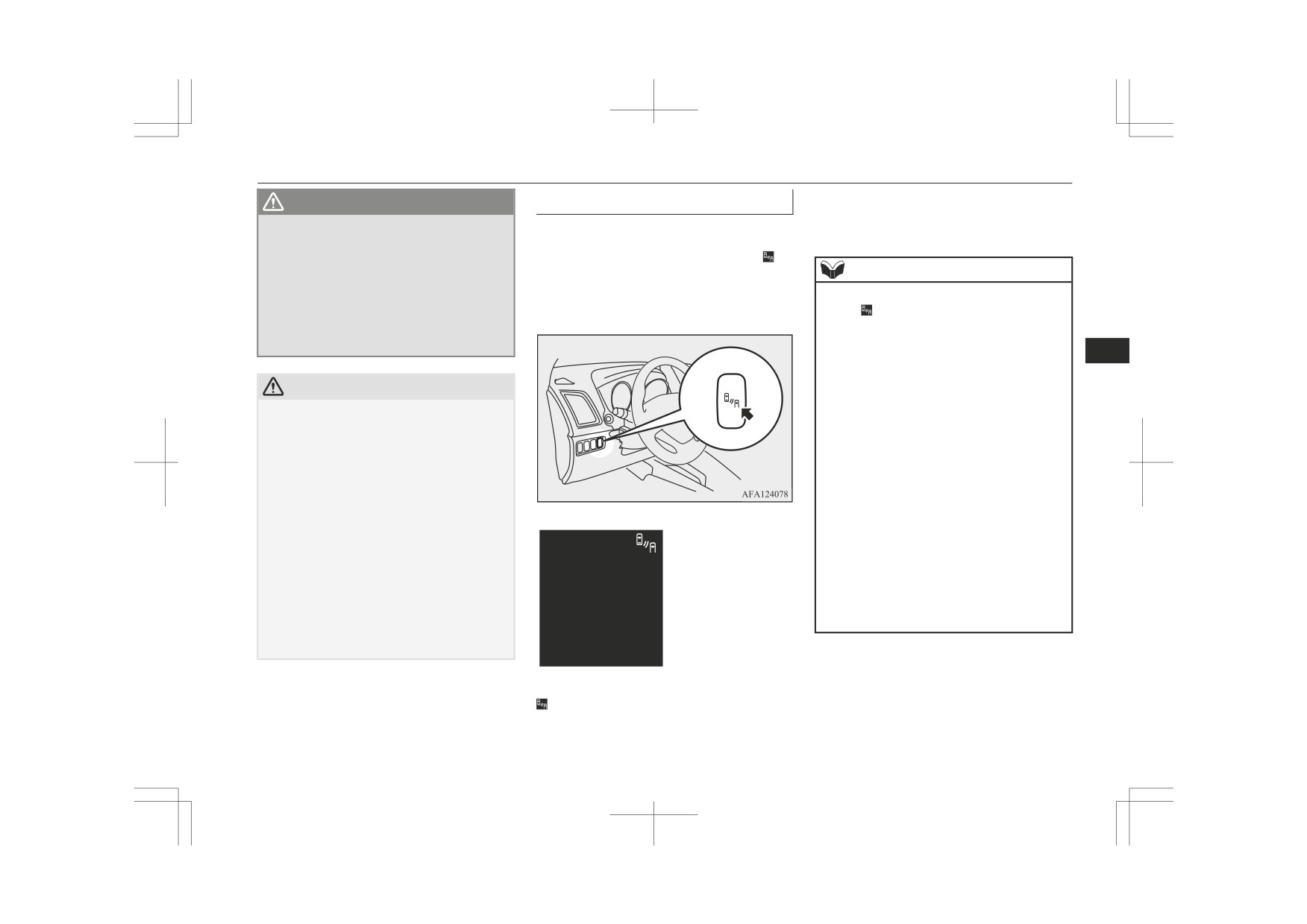
When the BSW switch is pressed while the
• When the bumper surface around the
the same time.
sensor is covered with dirt, snow and
ignition switch is turned to the “ON” position
ice, etc.
or the operation mode is put in ON, the in-
• When a bicycle carrier or accessory is
dicator (green) will appear on the information
NOTE
installed to the rear of the vehicle.
screen of the multi-information display and
z
After the system check screen disappears,
• When the sensor is extremely hot or
the BSW will enter the standby state.
the
indicator (green) appears on the infor-
cold (while the vehicle is parked for a
mation screen of the multi-information dis-
long period of time under a blazing sun
play.
or in cold weather).
Refer to “Information screen (when the igni-
6
tion switch is turned from the “LOCK” posi-
tion to the “ON” position or the operation
CAUTION
mode is changed from OFF to ON)” on page
z
To maintain proper performance of the
5-08.
BSW, follow the instructions below.
When the ignition switch is turned to the
z
• Always clean the bumper surface around
“LOCK” position or the operation mode is
the sensor.
set to OFF, the selected condition
(BSW
• Avoid impacting the sensor or its sur-
ON/OFF) just before setting to OFF is re-
rounding area.
tained.
• Do not put a sticker on the sensor or its
The BSW operates when all of the following
z
surrounding bumper surface.
conditions are met.
• Do not paint the sensor or its surrounding
• The ignition switch is turned to the “ON”
bumper surface.
position or the operation mode is put in
• Do not modify the sensor or its surround-
ON.
ing area.
• The selector lever is in positions other
z
If the bumper has experienced an impact, the
than “P” (Park) and “R” (Reverse).
sensor may have been damaged and the
• The speed of your vehicle is approximate-
BSW may not function properly. Have the
ly 10 km/h or higher.
vehicle inspected at a MITSUBISHI
MOTORS Authorized Service Point.
When the BSW switch is pressed again, the
indicator on the information screen of the
multi-information display will then go out
and the BSW will turn off.
Starting and driving
6-65
Blind Spot Warning (BSW) (with Lane Change Assist)*
When the sensor detects an ap-
NOTE
When there is a malfunction in
proaching vehicle
the system or the sensor
• When driving near the entrance and outlet
When the indicator (green) appears on the
of a tunnel or very near the wall or near
the evacuation area inside a tunnel.
information screen of the multi-information
• When turning at an intersection in a town
display, if a vehicle is approaching your vehi-
area.
cle in the detection area, the BSW lamp in
• Under adverse weather conditions (rain,
the outside rear-view mirror illuminates.
snow, sand storm etc.).
If the turn-signal lever is operated to the side
• When driving while your vehicle is blow-
where the BSW lamp is illuminated, the
ing up water, snow, sand, etc., on the
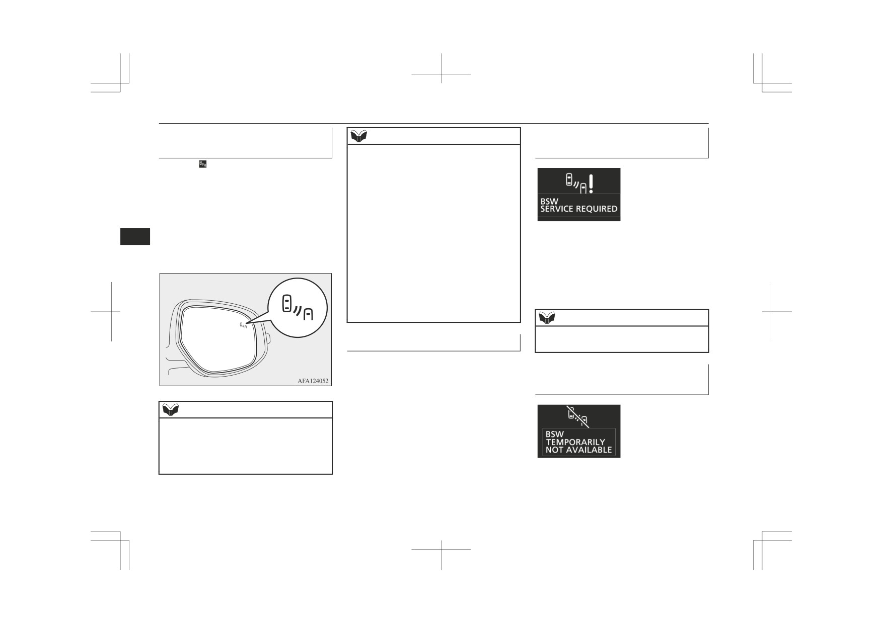
When the warning display appears, the BSW
6
BSW lamp will blink and the system will
road.
does not operate normally because there are
beep 3 times to alert the driver.
• When driving near a kerb, pothole and
some malfunctions in the system or the sen-
tramline.
sor. Have the vehicle inspected at a
z Set the BSW to OFF when towing.
MITSUBISHI MOTORS Authorized Service
z The BSW lamp in the outside rear-view mir-
Point as soon as possible.
ror may not be visible due to strong direct
sunlight or the glare from the headlamps of
vehicles behind you during night driving.
NOTE
z When the warning display appears, the BSW
System problem warning
will be deactivated.
If a problem occurs with the system, a visual
warning specific to the type of the problem is
When the sensor is temporarily
given together with an audible alarm.
not available
The warnings are combined with the Rear
Cross Traffic Alert (RCTA) system.
NOTE
z The BSW lamp in the outside rear-view mir-
ror may come on or blink in the following
conditions.
• When driving very near the guardrail or a
concrete wall.
6-66
Starting and driving
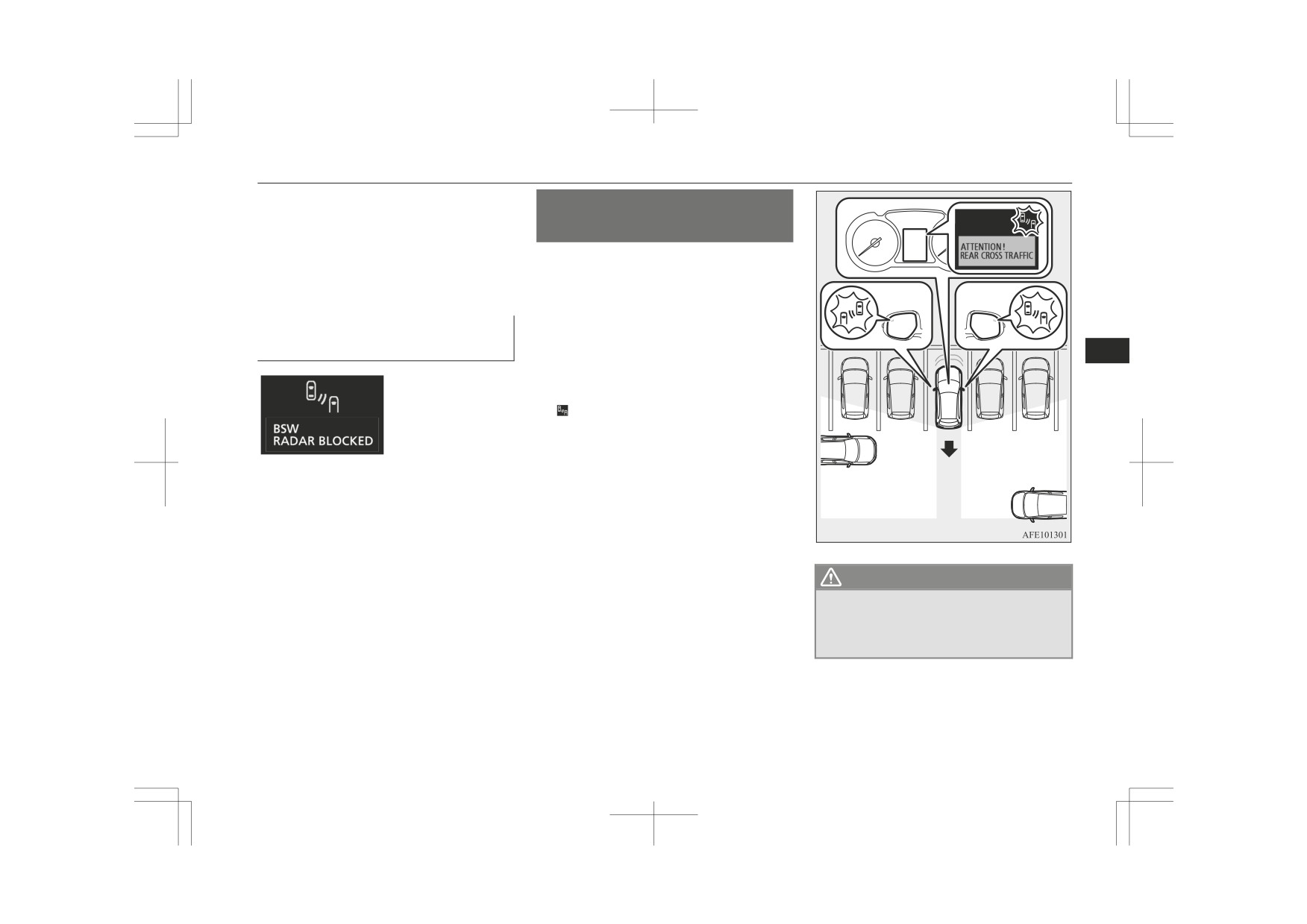
Rear Cross Traffic Alert (RCTA)*
When the warning display appears, the sensor
Rear Cross Traffic Alert
is temporarily not available for some reason
(RCTA)*
such as the environmental condition or in-
crease of the sensor temperature. When the
The Rear Cross Traffic Alert (RCTA) is an
warning display does not disappear after
aid system for backing up. When the RCTA
waiting for a while, contact a MITSUBISHI
system detects vehicles approaching from the
MOTORS Authorized Service Point.
sides while your vehicle is reversing, the
When there are foreign objects
Blind Spot Warning lamps in the outside rear-
on the sensor
view mirrors on both sides will blink and a
6
buzzer will sound to alert the driver. A warn-
ing message will appear on the information
screen of the multi-information display and
the indicator will be changed from green to
flashing in yellow.
When the warning display appears, the sensor
cannot detect a vehicle travelling side by side
or an approaching vehicle, because foreign
objects, such as dirt, snow or ice, adhere to
the bumper surface around the sensor.
Remove dirt, freezing or foreign material on
the bumper surface around the sensor.
WARNING
When the warning display does not disappear
z Before using the RCTA, read this entire
after having cleaned the sensor, contact a
section to fully understand the limitations
MITSUBISHI MOTORS Authorized Service
of this system. Failure to follow instruc-
Point.
tions could result in an accident.
Starting and driving
6-67

Rear Cross Traffic Alert (RCTA)*
WARNING
Detection areas
CAUTION
Never rely solely on the RCTA when
The detection area is shown as illustrated.
z
• When the speed of an approaching vehicle
backing up. The RCTA is an aid system.
is approximately 7 km/h (4 mph) or less.
It is not a substitute for your safe and
• If the sensor detection area is blocked by
careful driving. Always check visually be-
a nearby object, such as a wall or parked
hind and all around your vehicle for other
vehicle.
vehicles, persons, animals or obstructions.
• When a vehicle is approaching from
The performance of the RCTA may vary
straight behind your vehicle.
depending on driving, traffic and/or sur-
• When your vehicle is exiting from an an-
rounding conditions.
gled parking spot.
6
NOTE
z
The Blind Spot Warning lamps in the outside
rear-view mirrors on both sides will blink,
even when only one vehicle is approaching
from one side.
z
If a system problem, etc., is detected after
the RTCA warning message appears on the
information screen in the multi-information
display, the information screen may change
• Immediately after the RCTA has been
to another warning message.
turned on.
• Immediately after the operation mode has
been put in ON.
• When the bumper surface around the sen-
sor is covered with dirt, snow and ice, etc.
When the sensor becomes extremely hot
•
CAUTION
or cold, such as after the vehicle has been
parked for a prolonged time under the
z
In certain situations, the RCTA may not de-
blazing sun or in cold weather.
tect a vehicle in the detection areas. Some of
these situations include:
• When the reversing speed of your vehicle
is approximately
18 km/h (11 mph) or
higher.
6-68
Starting and driving

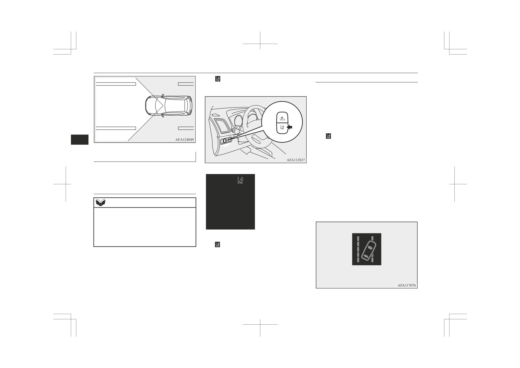
Lane Departure Warning (LDW)*
CAUTION
NOTE
Lane Departure Warning
z If the bumper has experienced an impact, the
z After the system check screen disappears,
(LDW)*
sensor may have been damaged and the
the
indicator (green) appears on the infor-
RCTA may not function properly. Have the
mation screen of the multi-information dis-
By recognizing through a sensor (A) the lane
vehicle inspected at a MITSUBISHI
play.
in which your vehicle is running, the Lane
MOTORS Authorized Service Point.
Refer to “Information screen (when the igni-
Departure Warning (LDW) gives you a warn-
tion switch is turned from the “LOCK” posi-
ing when your vehicle is likely to drift from
tion to the “ON” position or the operation
To operate
its lane with an audible alarm and a visual
mode is changed from OFF to ON)” on page
5-08.
alarm displayed on the information screen of
1. Press the BSW switch while the opera-
6
the multi-information display.
tion mode is put in ON.
z Set the RCTA to OFF when towing.
For details about handling the sensor, refer to
(Refer to “Blind Spot Warning (BSW):
z The Blind Spot Warning lamp in the outside
rear-view mirror may appear not to be on
“Handling of the sensor” on page 6-56.
To operate” on page 6-65.)
due to strong direct sunlight or the glare
2. When the gearshift lever and the selector
from the headlamps of vehicles behind you
lever is moved to the “R” (REVERSE)
during night driving.
position, the RCTA will operate.
When a problem is detected in
CAUTION
the system
z Within approximately 7 seconds after the ig-
If the system detects a problem, a warning is
nition switch is turned to the “ON” position
or the operation mode is put in ON, a warn-
displayed on the information screen in the
ing message will not appear on the informa-
multi-information display.
tion screen of the multi-information display
Refer to “Blind Spot Warning (BSW): Sys-
even if the system detects a vehicle ap-
tem problem warning” on page 6-66.
proaching your vehicle.
Starting and driving
6-69
Lane Departure Warning (LDW)*
The indicator will appear on the informa-
Standby state
tion screen of the multi-information display.
In the standby mode, the system is capable of
recognizing the lane in which your vehicle is
positioned and issuing audible warning when
your vehicle goes out of the lane.
The system automatically shifts from the
“ON” state to the standby state if all of the
following conditions are simultaneously met.
The indicator on the information screen in
6
the multi-information display will be changed
to green.
How to operate LDW
z The vehicle speed is approximately 65
km/h or higher.
The indication on the information screen of
z The turn-signal lever is not operated.
the multi-information display changes as fol-
lows depending on the state of the system.
z The hazard lamp is not activated.
z Environmental conditions are adequate
To turn on/off the LDW
for the system to recognize the lane
markings on both sides.
NOTE
z The system has been placed in the “ON”
state.
z The LDW is turned on when the vehicle is
shipped from the factory.
z The currently selected LDW setting (on or
off) is stored even when the ignition switch
is turned to the “LOCK” position or the op-
To turn off the LDW, press the LDW switch.
eration mode is put in OFF.
The indicator on the information screen of
the multi-information display will then go
To turn on the LDW, press the LDW switch.
out. To return the LDW to “ON”, press the
LDW switch again.
(green)
6-70
Starting and driving
Lane Departure Warning (LDW)*
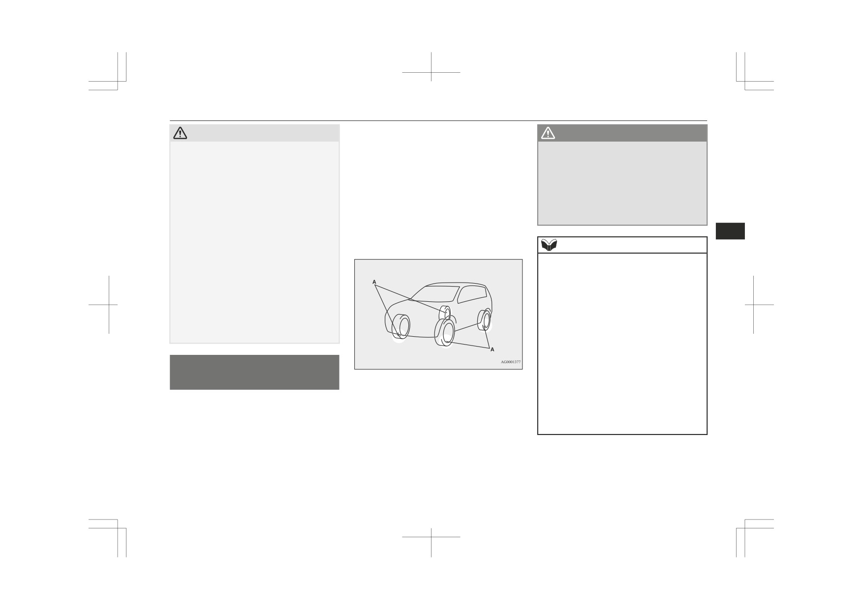
NOTE
NOTE
Windscreen is dirty
The alarm shown below is displayed if the
z The system stays in the “ON” state for ap-
z If the lane markers are only on one side of
proximately 7 seconds after the hazard lamp
the road, the LDW will operate only for the
system becomes temporarily unavailable due
has stopped flashing or the turn-signal lever
appropriate side where the lane marker is
to dirt on the windscreen at the sensor por-
has returned to the home position.
drawn.
tion.
After having cleaned the windscreen, the sys-
tem will automatically return to operation.
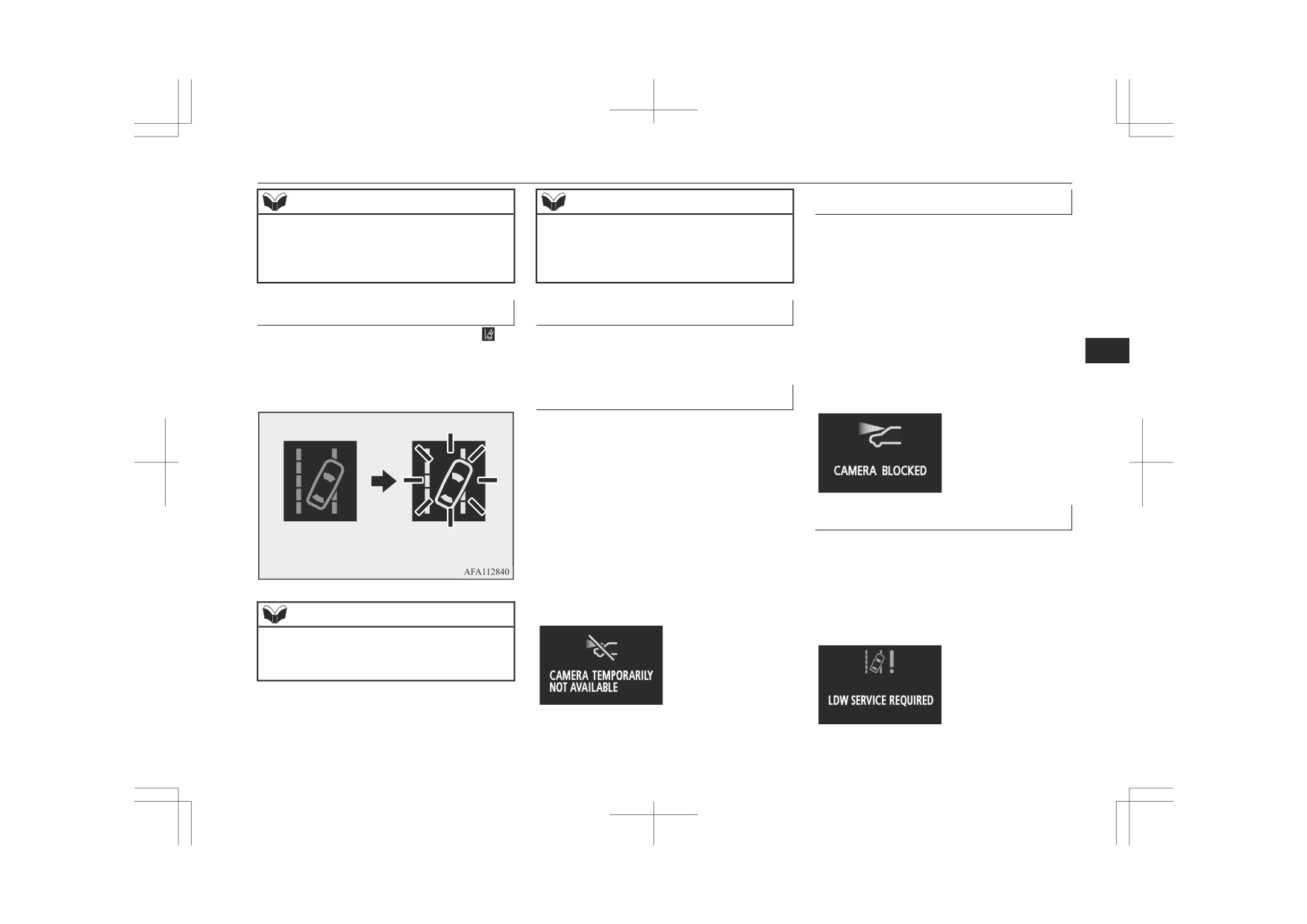
Lane departure warning
System problem warning
If the alarm continues showing, there is a
A buzzer sounds intermittently and the in-
If a problem occurs with the system, a visual
possibility that the sensor has a malfunction.
dicator starts flashing in yellow when your
warning specific to the type of the problem is
6
Contact a MITSUBISHI MOTORS Author-
vehicle is about to leave or has left the lane in
given together with an audible alarm.
ized Service Point for inspection of the sen-
the standby mode.
sor.
Too hot or cold sensor
The alarm shown below is displayed if the
system becomes temporarily unavailable due
to a too high or low temperature of the sen-
sor.
If the temperature of the sensor reaches the
predetermined value, the system automatical-
ly recovers the normal state.
LDW deactivation due to fault
(green)
(flashing in yellow)
If the alarm continues showing, there is a
The alarm shown below is displayed if the
possibility that the LDW has a malfunction.
LDW goes into a non-initialized state due to
Contact a MITSUBISHI MOTORS Author-
a fault.
ized Service Point for inspection of the sys-
If
this
happens, please contact a
tem.
MITSUBISHI MOTORS Authorized Service
NOTE
Point for inspection of the system.
z If the warning continues for approximately 3
seconds or more, the system switches to the
standby mode before the warning stops.
Starting and driving
6-71
Lane Departure Warning (LDW)*
CAUTION
CAUTION
• When driving on a road whose lane mark-
• When entering a junction or other point of
ings (white or yellow) are worn out or
road where lanes are laid out complicated-
smeared with dirt to an extent not recog-
ly.
nizable by the system.
• When passing a road section where the
• When lane markings are vague, typically
number of lanes increases/decreases or
during a drive in the rain, snow, fog or
multiple lanes are crossing each other.
NOTE
dark area, or when running against the
• When the lane is marked by double or
sun.
otherwise special lines.
z
If the sensor or its surrounding area reaches
• When the vehicle is moving in a place
• When driving on a winding or rough road.
6
an extremely high temperature when parking
where lane markings are interrupted, such
• When driving on a slippery road covered
the vehicle under a blazing sun, the “LDW
as a toll booth entrance and motorway
by rain water, snow, ice, etc.
SERVICE REQUIRED” message may ap-
junction.
• When passing through a place where the
pear.
• When running on a road portion with in-
brightness suddenly changes, like the inlet
If the message remains even after the tem-
completely removed old lane markings,
or outlet of a tunnel.
perature of the sensor or its surrounding area
shadows, lingering snow, truck-like pud-
• When turning steep curves.
has been in range, please contact a
dles mistakable for lane markings (espe-
MITSUBISHI MOTORS Authorized Serv-
• When the road surface is reflecting the
cially after the rain when road surface is
ice Point.
light shining from the direction opposite
reflecting light) or similar confusing fac-
to the running direction.
tors.
• Vehicle largely lurches when it is running
• When running in a lane other than the
over steps or other irregularities of the
CAUTION
cruising lane and passing lane.
road surface.
z
LDW has its performance limitations. Do
• When running beside a closed lane sec-
• When the headlamp illumination is inade-
not over-rely on the system.
tion or in a provisional lane in a traffic
quate because of contaminated or deterio-
z
LDW is not designed to lessen risks associ-
work zone.
rated lenses or improperly aimed head-
ated with not looking ahead carefully (atten-
• When running in an extremely narrow
lamps.
tion drawn to something on the side, absent-
lane.
• When the vehicle is leaning much to one
mindedness, etc.) or poor visibility caused
• When the following distance between
side due to heavy luggage on it or improp-
by bad weather etc. Keep steering your vehi-
your vehicle and a vehicle in front be-
erly adjusted tyre pressures.
cle correctly and drive safely.
comes extremely reduced
(especially
• When oncoming vehicles’ headlamps
z
The system may not operate correctly in the
when a marking is hidden by a vehicle in
shine the sensor.
following conditions. If required, set the
front this is running too close to the mark-
LDW switch to “OFF.”
ing).
6-72
Starting and driving
Tyre pressure monitoring system (TPMS)*
The base tyre pressure can be set at desired
CAUTION
WARNING
value by the driver with the reset function ex-
• When the vehicle is equipped with non-
z
The spare wheel does not have a tyre in-
ecution. (The low pressure warning threshold
standard tyres
(including excessively
flation pressure sensor.
is set based on the reset.)
worn tyres and temporary spare tyre),
When the spare tyre is used, the tyre pres-
The tyre inflation pressure sensor IDs for two
uses snow traction device (tyre chains), or
sure monitoring system will not work
has non-specified components such as a
sets of tyres can be registered by a
properly.
modified suspension.
MITSUBISHI MOTORS Authorized Service
See a MITSUBISHI MOTORS Author-
• When the windscreen is covered with wa-
Point, and the valid ID set can be switched by
ized Service Point as soon as possible to
ter droplets, snow, dust, etc.
the multi-information meter switch (It’s bene-
replace or repair the original tyre.
z
Follow the instructions given below to keep
ficial in case of seasonal tyre change between
6
your LDW in good operating conditions.
summer tyre and winter tyre.)
• Always keep the windscreen clean.
NOTE
• Avoid applying a strong shock or pressure
z
The tyre pressure monitoring system
to the sensor. Do not attempt to detach or
(TPMS) is not a substitute for regularly
disassemble it.
checking tyre inflation pressures.
• Do not put anything like a sticker on the
Be sure to check the tyre inflation pressures
area in front of the sensor of the wind-
as described in “Tyres” on page 10-10.
screen.
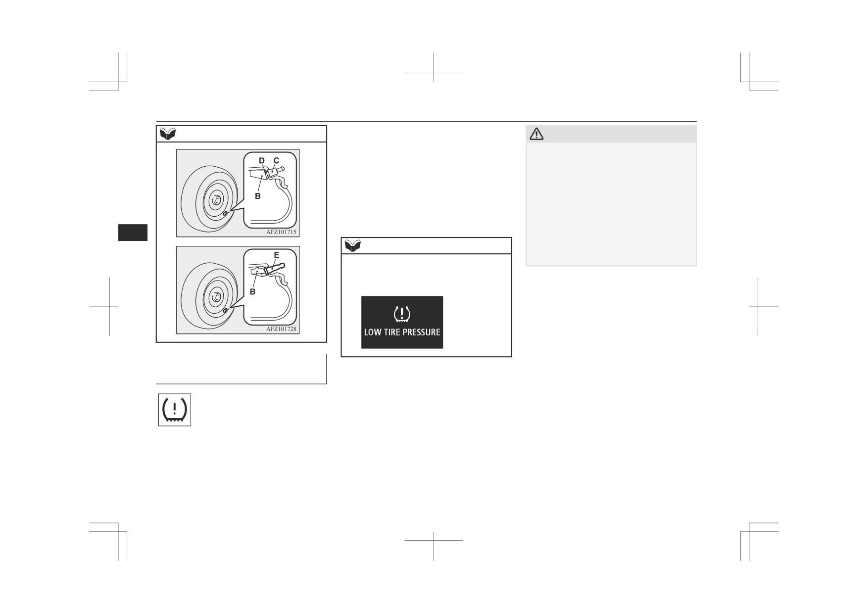
z
The tyre inflation pressure sensor (B) is in-
• Use only MITSUBISHI MOTORS GEN-
stalled in the illustrated location.
UINE parts when replacing the wind-
• On vehicles with Type 1 sensor which has
screen wipers.
the metallic air valve (C), replace grom-
met and washer (D) with a new one when
the tyre is replaced.
Tyre pressure monitoring
• On vehicles with Type 2 sensor which has
system (TPMS)*
the rubber air valve (E), replace rubber air
valve (E) with a new one when the tyre is
replaced.
The tyre pressure monitoring system (TPMS)
For details, please contact your
uses tyre inflation pressure sensors (A) on the
MITSUBISHI MOTORS Authorized
wheels to monitor the tyre inflation pressures.
Service Point.
The system only indicates when a tyre is sig-
nificantly under-inflated.
Starting and driving
6-73
Tyre pressure monitoring system (TPMS)*
NOTE
CAUTION
If one or more of the vehicle tyres (except for
the spare tyre) is significantly under-inflated,
z If the warning lamp does not illuminate
Type 1
when the ignition switch is turned to the
the warning lamp will remain illuminated
“ON” position or the operation mode is put
while the ignition switch or the operation
in ON, it means that the tyre pressure moni-
mode is in ON.
toring system (TPMS) is not working prop-
Refer to “If the warning lamp/display illumi-
erly. Have the system inspected by a
nates while driving” on page 6-76 and take
MITSUBISHI MOTORS Authorized Serv-
the necessary measurements.
ice Point.
In such situations, a malfunctioning of the
6
system may prevent the monitoring of the
NOTE
tyre pressure. Avoid sudden braking, sharp
Type 2
turning and high-speed driving.
z In addition, the warning display will be dis-
played on the information screen in the mul-
ti-information display.
The tyre pressure monitoring
system warning lamp/display
When the ignition switch is turned to the
“ON” position or the operation mode is put in
ON, the tyre pressure monitoring system
warning lamp normally illuminates and goes
off a few seconds later.
6-74
Starting and driving

Tyre pressure monitoring system (TPMS)*
Please note that the tyre pressure monitoring
CAUTION
NOTE
system (TPMS) is not a substitute for proper
z
If a malfunction is detected in the tyre pres-
tyre maintenance, and it is the driver’s re-
sure monitoring system (TPMS), the warn-
sponsibility to maintain correct tyre pressure,
ing lamp will blink for approximately 1 mi-
even if under-inflation has not reached the
nute and then remain continuously illumina-
ted.
level to trigger illumination of the tyre pres-
The warning lamp will issue further warn-
sure monitoring system
(TPMS) low tyre
ings each time the engine is restarted as long
pressure telltale.
as the malfunction exists.
Your vehicle has also been equipped with a
Check to see whether the warning lamp goes
Each tyre, including the spare (if so equip-
warning lamp to indicate when the system is
6
off after few minutes driving.
ped), should be checked monthly when cold
not operating properly.
If it then goes off during driving, there is no
and inflated to the inflation pressure recom-
The warning lamp is combined with the low
problem.
mended by the vehicle manufacturer on the
However, if the warning lamp does not go
tyre pressure telltale.
tyre inflation pressure label. (If your vehicle
off, or if it blinks again when the engine is
When the system detects a malfunction, the
has tyres of a different size than the size indi-
restarted, have the vehicle inspected by a
telltale will flash for approximately one mi-
cated on the tyre inflation pressure label, you
MITSUBISHI MOTORS Authorized Serv-
nute and then remain continuously illumina-
ice Point.
should determine the proper tyre inflation
ted. This sequence will continue upon subse-
In such situations, a malfunctioning of the
pressure for those tyres.)
quent vehicle start-ups as long as the mal-
system may be preventing the monitoring of
As an added safety feature, your vehicle has
function exists.
the tyre pressure. For safety reasons, when
been equipped with the tyre pressure moni-
When the warning lamp is illuminated, the
the warning lamp appears while driving,
toring system (TPMS) that illuminates a low
avoid sudden braking, sharp turning and
system may not be able to detect or signal
tyre pressure telltale when one or more of
high-speed driving.
low tyre pressure as intended.
your tyres is significantly under-inflated.
Accordingly, when the low tyre pressure tell-
NOTE
tale illuminates, you should stop and check
your tyres as soon as possible, and inflate
z
In addition, the warning display will be dis-
them to the proper pressure. Driving on a sig-
played on the information screen in the mul-
ti-information display.
nificantly under-inflated tyre causes the tyre
to overheat and can lead to tyre failure.
Under-inflation also reduces fuel efficiency
and tyre tread life, and may affect the vehi-
cle’s handling and stopping ability.
Starting and driving
6-75
Tyre pressure monitoring system (TPMS)*
The tyre pressure monitoring system (TPMS)
NOTE
CAUTION
malfunctions may occur for a variety of rea-
z
After inspecting or adjusting the tyre pres-
z
The warning lamp/display may not illumi-
sons, including the installation of replace-
sure, always reinstall the valve cap on the
nate immediately in the event of a tyre blow-
ment or alternate tyres or wheels on the vehi-
valve stem.
out or rapid leak.
cle that prevent the tyre pressure monitoring
Without the valve cap, dirt or moisture could
system (TPMS) from functioning properly.
get into the valve, resulting in damage to the
Always check the tyre pressure monitoring
tyre inflation pressure sensor.
NOTE
system (TPMS) malfunction telltale after re-
z
Do not use metal valve caps, which may
z
To avoid the risk of damage to the tyre infla-
placing one or more tyres or wheels on your
cause a metal reaction, resulting in corrosion
tion pressure sensors, have any punctured
and damage of the tyre inflation pressure
6
vehicle to ensure that the replacement or al-
tyre repaired by a MITSUBISHI MOTORS
sensors.
ternate tyres and wheels allow the tyre pres-
Authorized Service Point. If the tyre repair is
z
Once adjustments have been made, the
sure monitoring system (TPMS) to continue
not done by a MITSUBISHI MOTORS Au-
warning lamp will go off after a few minutes
to function properly.
thorized Service Point, damage to the tyre
of driving.
inflation pressure sensor is not covered by
If the warning lamp/display il-
your warranty.
2. If the warning lamp remains illuminated
z
Do not use an aerosol puncture-repair spray
luminates while driving
after you have been driving for about 10
on any tyre.
1. If the warning lamp illuminates, avoid
Such a spray could damage the tyre inflation
minutes after you adjust the tyre infla-
hard braking, sharp steering manoeuvres
pressure sensors.
tion pressure, one or more of the tyres
Have any puncture repaired by a
and high speeds. You should stop and
may have a puncture. Inspect the tyre
MITSUBISHI MOTORS Authorized Serv-
adjust the tyres to the proper inflation
and if it has a puncture, have it repaired
ice Point.
pressure as soon as possible. Adjust the
by a MITSUBISHI MOTORS Author-
z
Using the tyre repair kit may damage the
spare tyre at the same time. Refer to
ized Service Point as soon as possible.
tyre inflation pressure sensor. The vehicle
“Tyres” on page 10-10
must promptly be inspected and repaired by
a MITSUBISHI MOTORS Authorized Serv-
WARNING
ice Point.
NOTE
z
If the warning lamp/display illuminates
z In addition, the warning display will be dis-
while you are driving, avoid hard brak-
The tyre pressure monitoring system (TPMS)
played on the information screen in the mul-
ing, sharp steering manoeuvres and high
may not work normally in the following cir-
ti-information display.
speeds.
cumstances:
z When inspecting or adjusting the tyre pres-
Driving with an under-inflated tyre ad-
sure, do not apply excessive force to the
versely affects vehicle performance and
z A wireless facility or device using the
valve stem to avoid breakage.
can result in an accident.
same frequency is near the vehicle.
6-76
Starting and driving

Tyre pressure monitoring system (TPMS)*
z
Snow or ice is stuck inside the fenders
Whenever the tyres and wheels
1. Operate the multi-information meter
and/or on the wheels.
switch to switch the information screen
are replaced with new ones
z
The tyre inflation pressure sensor’s bat-
to the menu screen.
If new wheels with new tyre inflation pres-
tery is dead.
Refer to
“Multi information display
sure sensors are installed, their ID codes must
z
Wheels other than MITSUBISHI
switch” on page 5-05.
be programmed into the tyre pressure moni-
MOTORS GENUINE wheels are being
Refer to “Changing the function settings
toring system. Have tyre and wheel replace-
used.
(when the ignition switch or the opera-
ment performed by a MITSUBISHI
z
Wheels that are not fitted with tyre infla-
tion mode is ON)” on page 5-17.
MOTORS Authorized Service Point to avoid
tion pressure sensors are being used.
2. Lightly press the multi-information me-
the risk of damaging the tyre inflation pres-
z
Wheels whose ID codes are not memo-
ter switch to select “
” (reset
6
sure sensors. If the wheel replacement is not
rized by the vehicle are used.
of low tyre pressure warning threshold).
done by a MITSUBISHI MOTORS Author-
z
A window tint that affects the radio
3. Press and hold the multi-information
ized Service Point, it is not covered by your
wave signals is installed.
meter switch for approximately 3 sec-
warranty.
onds or more, the buzzer sounds.
NOTE
CAUTION
z
Tyre inflation pressures vary with the ambi-
ent temperature. If the vehicle is subjected to
z The use of non-genuine wheels will prevent
large variations in ambient temperature, the
the proper fit of the tyre inflation pressure
tyre inflation pressures may be low (causing
sensors, resulting air leakage or damage of
the warning lamp/display to come on) when
the sensors.
the ambient temperature is relatively low. If
the warning lamp/display comes on, adjust
Reset of low tyre pressure
the tyre inflation pressure.
warning threshold
The threshold is set based on the tyre pres-
sure which the reset function is executed by
4. The warning lamp start flashing slowly.
following procedure.
5. Drive for a while. The reset is completed
if the warning lamp goes out.
Starting and driving
6-77
Reversing sensor system*
3. Press and hold the multi-information
NOTE
Reversing sensor system*
meter switch for approximately 3 sec-
z The reset function should be executed every
onds or more. The setting changes the
This system operates when you are backing
time when the tyre pressure or tyre rotation
selected tyre ID set.
is adjusted.
the vehicle. It uses corner and back sensors to
z The reset function should be executed when
detect an obstacle and the information screen
the tyre is cold. If it is executed when the
in the multi-information display and the buz-
tyre is warm (e.g. after driving), there may
zer to inform you of the approximate distance
be a low tyre pressure warning earlier than
to the obstacle.
usual.
6
CAUTION
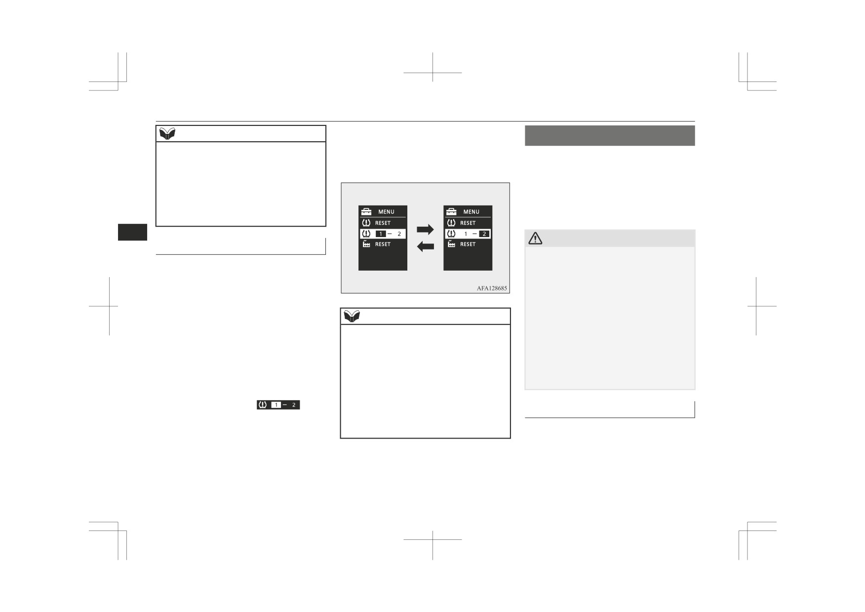
Tyre ID set change
z The reversing sensor system assists you in
In case that 2 sets of tyre inflation pressure
determining the approximate distance be-
sensor ID are registered in the receiver, the
tween the vehicle and an obstacle located
valid tyre ID set can be changed by following
behind the vehicle. It has limitations in terms
procedure.
of detectable areas and objects, and may not
1. Operate the multi-information meter
properly detect some objects. Therefore, do
not place excessive confidence in the revers-
switch to switch the information screen
NOTE
ing sensor system and operate the vehicle as
to the menu screen.
z
Each time this procedure is done, the tyre ID
carefully as you would do with a vehicle not
Refer to
“Multi information display
set is changed. (1 - 2 - 1 - 2 …)
equipped with this system.
switch” on page 5-05.
z
The tyre ID set is NOT changed, in case that
z Make sure to check the surroundings with
Refer to “Changing the function settings
only 1 set of ID is registered.
your own eyes to ensure safety. Do not oper-
(when the ignition switch or the opera-
z
When changing the tyre ID set, the reset
ate the vehicle by relying on the reversing
tion mode is ON)” on page 5-17.
function of low tyre pressure warning
sensor system alone.
2. Lightly press the multi-information me-
threshold is automatically started.
(The
warning lamp starts flashing slowly.) If the
ter switch to select “
” (tyre
tyre is warm at this time, the reset function
Obstacle detection areas
ID set change).
should be executed again when the tyre is
The detection areas of the corner and back
cold.
sensors are limited to those shown in the il-
lustration. Moreover, the sensors are unable
to detect low or thin objects or objects near
the rear bumper. Thus, make sure to check
the surroundings as you operate the vehicle in
a safe manner.
6-78
Starting and driving

Reversing sensor system*
Corner and back sensor loca-
Vehicles without a towing bar
Vehicles with a towing bar
tions
The detection areas are within approximately
The detection areas are within approximately
There are two corner sensors (A) at the cor-
60 cm (A) from the corner sensors, 150 cm
60 cm (A) from the corner sensors, 150 cm
ners of the rear bumper, and two back sensors
(B) from the back sensors, and 60 cm (C) or
(B) from the back sensors, and 60 cm (C) or
(B) in the centre of the rear bumper.
less from the ground surface, excluding the
less from the ground surface, excluding the
area approximately
10 cm
(D) from the
area approximately
10 cm
(D) from the
ground surface.
ground surface. The non-detection areas (E)
are within approximately 20 cm (F) from the
bumper.
6
Reversing sensor system detec-
tion areas
Depending on whether the vehicle is equip-
ped with a towing bar, you can change the re-
versing sensor system between the standard
NOTE
mode and the towing bar mode. The towing
z If the rear bumper has been exposed to an
bar mode changes the system to exclude the
impact, the corner or back sensors may fail
area in which the towing bar is mounted from
and prevent the system from functioning
the detection areas.
properly. Have the vehicle inspected at a
MITSUBISHI MOTORS Authorized Serv-
ice Point.
Starting and driving
6-79
Reversing sensor system*
NOTE
CAUTION
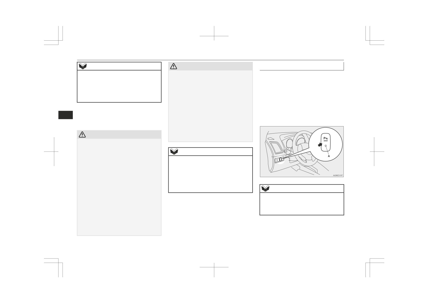
To operate
To operate the system, move the gearshift
z The sensors do not detect objects located in
• The sensors or surroundings have been
the area directly below or near the bumper.
wiped by hand, or stickers or accessories
lever or selector lever to the
“R” position
If the height of an object is lower than the
have been attached.
while the ignition switch or the operation
mounted position of the corner or back sen-
z
The reversing sensor system may not proper-
mode is in ON. When the reversing sensor
sors, the sensors may not continue detecting
ly detect the following:
system is operated, the reversing sensor sys-
it even if they detected it initially.
• Objects that are thin, such as wire nets or
tem operation indication lamp (A) will turn
ropes.
on. To stop the operation, push the “SONAR”
• Objects that absorb sound waves, such as
For information on how to change the detec-
switch; the reversing sensor system operation
snow.
6
tion areas, please refer to “Changing the de-
• Objects that are shaped with a sharp an-
indication lamp (A) is turned off.
tection areas” on page 6-81.
gle.
• Objects with a smooth surface, such as
glass.
CAUTION
• Objects that are low, such as kerbstones.
z
The reversing sensor system may not operate
properly under the following conditions:
• The sensors or surroundings are covered
NOTE
with ice, snow, or mud.
z
The buzzer may sound lower than the nor-
• The sensors are frozen.
mal warning sound when the reversing sen-
• The system receives ultrasonic noise from
sor system is receiving ultrasonic noise from
other sources (the horns of other vehicles,
other sources, but this is not a malfunction.
motorcycle engines, brakes, radios, pour-
The buzzer will stop sounding and the sys-
ing rain, splashing water, tyre chains,
tem will return to normal operation after the
etc.).
noise is no longer received.
NOTE
• The sensors are extremely hot or cold
(while the vehicle is parked for a long pe-
z
Only when the gearshift lever or selector
riod of time under a blazing sun or in cold
lever is in the
“R” position, the reversing
weather).
sensor system can be operated or be stopped
• The vehicle tilts significantly.
by using the “SONAR” switch.
• The vehicle is driven on a rough road
(with a bumpy, gravel, hilly, or grassy sur-
face).
• The vehicle is too close to an obstacle.
6-80
Starting and driving

Reversing sensor system*
Warning for obstacles
Back sensor
(vehicles without a towing
NOTE
bar)
If there is an obstacle behind the vehicle, a
z When the sensors detect different obstacles
warning will be issued with the information
Vehicle to obstacle
Warning display/
at the same time, the information screen in
screen in the multi-information display and a
distance
sound cycle
the multi-information display indicates the
warning buzzer.
directions of the obstacles each sensor is de-
Approx. 150 to
Intermittent
tecting. However, closer obstacles are given
80 cm
priority over other detected obstacles and the
warning buzzer sounds to inform you of
Approx. 80 to 40 cm
Fast intermittent
closer obstacles.
Within approx.
Continuous
6
40 cm
Changing the detection areas
Back sensor (vehicles with a towing bar)
The detection areas can be changed as fol-
lows:
Vehicle to obstacle
Warning display/
distance
sound cycle
Vehicles with a towing bar
Approx. 150 to
Intermittent
While the operation of the system is stopped
100 cm
at the “SONAR” switch, push the “SONAR”
switch approximately 3 seconds or more, and
1- Corner sensor (left)
Approx. 100 to
Fast intermittent
release it. The buzzer sounds twice to indi-
2- Back sensor
60 cm
cate that the detection area has been changed.
3- Corner sensor (right)
Approx. 60 to 40 cm
Continuous
Vehicles without a towing bar
Corner sensor
Within approx.
None
While the operation of the system is stopped
40 cm
Vehicle to obstacle
Warning display/
at the “SONAR” switch, push the “SONAR”
distance
sound cycle
switch approximately 3 seconds or more, and
CAUTION
release it. The buzzer sounds once to indicate
Approx. 60 to 40 cm
Intermittent
that the detection area has been changed.
z The distances given are to be used for refer-
Approx. 40 to 25 cm
Fast intermittent
ence only, as errors may be caused by vari-
ous factors, such as temperature, humidity,
Within approx.
Continuous
or the shape of the obstacles.
25 cm
Starting and driving
6-81

Rear-view camera*
NOTE
Reversing sensor system warn-
CAUTION
ing display
z
The detection area will not change if you
z The rear-view camera is an assistance sys-
keep the
“SONAR” switch pushed for
In case there is a malfunction in the reversing
tem that enables the driver to check for ob-
10 seconds or more.
stacles behind the vehicle. Its range of view
sensor system, the display for the malfunc-
z
After pushing the “SONAR” switch, revers-
is limited, so you should not overly depend
tioning sensor will blink and the warning
ing sensor system operation differs accord-
on it. Please drive just as carefully as you
buzzer will sound for approximately 5 sec-
ing to the detection area setting.
would if the vehicle did not have the rear-
onds. Even after the buzzer has stopped
• Setting when towing bar is not equipped
view camera.
When the gearshift lever or selector lever
sounding, the display will continue blinking
z Be sure to visually confirm safety around the
is moved to the “R” position, the revers-
until the system reverts to the normal state.
vehicle with your own eyes. Do not depend
6
ing sensor system will operate even if cor-
Have the vehicle inspected at a
entirely on the rear-view camera.
ner sensor operation was stopped by push-
MITSUBISHI MOTORS Authorized Service
ing the “SONAR” switch.
Point.
Range of view of rear-view
• Setting when towing bar is equipped
When reversing sensor system operation
camera
was stopped by pushing the “SONAR”
Example: Corner sensor (left) malfunctioning
switch, the reversing sensor system will
The range of view of the rear-view camera is
not operate until the engine has been stop-
limited to the area shown in the illustrations.
ped even if the gearshift lever or selector
It cannot show both sides and the lower part
lever is moved to the “R” position.
of the rear bumper, etc.
To resume reversing sensor system opera-
When reversing, be sure to visually confirm
tion, push the “SONAR” switch or stop
safety around the vehicle.
and restart the engine, and then move the
gearshift lever or selector lever to the “R”
position.
Rear-view camera*
The rear-view camera is a system that shows
the view behind the vehicle on the screen of
the DISPLAY AUDIO, the Smartphone-link
Display Audio (SDA) or the Smartphone-link
Display Audio (SDA) navigation system.
6-82
Starting and driving