Mitsubishi Outlander XL. Manual - part 978


  Index      Mitsubishi     Mitsubishi Outlander XL - service repair manual 2007 year


Search            copyright infringement  


Content   ..  976  977  978  979   ..


Mitsubishi Outlander XL. Manual - part 978


Display contents

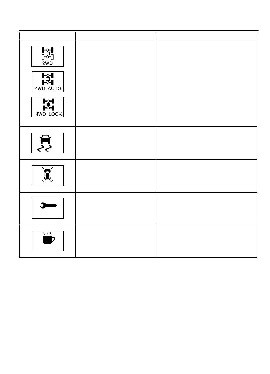
System operation state

Action procedure

ZC602332

ZC602333

ZC602334

ZC6023350000

Displays the screen in accordance
with  operation  state  of  the  AWD
selector switch.

If  the  AWD  selector  switch  position  and
screen do not agree with each other, perform
the  troubleshooting  for  the  AWD.  Refer  to
GROUP 27C, Diagnosis P.27C-74.

ZC6023360000

Displayed  when  the  ASC  is  in
operation.

If  the  warning  screen  is  not  displayed
normally  or  if  the  screen  continues  to  be
displayed, perform the troubleshooting for the
ASC.  Refer  to  GROUP  35C,  Symptom
Chart P.35C-160.

ZC6023370000

Displayed when the corner sensor
detects obstacles.

If the screen is not displayed even when the
obstacle  is  in  a  distance  that  the  detection
should  be  made,  or  if  there  is  an  abnormal
display,  perform  the  troubleshooting  for  the
corner sensor system. Refer to P.54Ab-40.

PERIODIC
        INSPECTION

ZC6023380000

Displayed  when  the  set  period
elapses.

-

REST REMINDER

ZC6023390000

Displayed  when  the  set  time
elapses.

-

ON-VEHICLE SERVICE

SPEEDOMETER CHECK

M15410100038USA0000010000

1.

Adjust  the  pressure  of  tires  to  the  specified  level  (Refer  to
GROUP 31, On-vehicle Service P.31-7).

2.

Where applicable, ensure that the TPMS warning light is not
illuminating or flashing.

COMBINATION METER

54Ab-65

ON-VEHICLE SERVICE

Do not accelerate or decelerate suddenly during servicing
work.

ZC6033440000

<FWD>

WHEEL CHOCKS

Set a free-roller on the rear tire for AWD.

3.

For FWD vehicles, set the vehicle onto a speedometer tester
and use wheel chocks to hold the rear wheels.

ZC6033450000

FREE ROLLER

<AWD>

4.

For AWD vehicles, set the vehicle onto a speedometer tester
and place the rear wheels on a free roller.

ZC5012710000

FRONT

ANCHOR PLATE

PULLER

5.

To  prevent  the  front  wheel  from  moving  from  side  to  side,
attach  tension  bars  to  the  tie-down  hook,  and  secure  both
ends to anchor plates.

6.

To prevent the vehicle from moving, attach a chain or wire to
the rear retraction hook, and make sure the end of the chain
or wire is secured.

7.

Check  if  the  speedometer  indicator  range  is  within  the
standard values.

Standard value <Except vehicles for CANADA>:

Standard indication mph
(km/h)

Allowance range mph (km/
h)

10 (16)

8.5 - 11.5 (13.6 - 18.4)

25 (40)

23.5 - 26.5 (37.6 - 42.4)

50 (80)

48.5 - 51.5 (77.6 - 82.4)

75 (120)

73.5 - 76.5 (117.6 - 122.4)

100 (161)

98.5 - 102.5 (158.6 - 165.0)

125 (201)

123.5 - 127.5 (198.6 - 205.0)

Standard value <Vehicles for CANADA>:

standard indication km/h
(mph)

Allowance range km/h
(mph)

20 (12.4)

19 - 24 (11.8 - 14.9)

40 (24.8)

40 - 44 (24.8 - 27.3)

80 (49.7)

80 - 85 (49.7 - 52.8)

120 (74.6)

120.5 - 125.5 (74.9 - 78.0)

54Ab-66

COMBINATION METER

ON-VEHICLE SERVICE

standard indication km/h
(mph)

Allowance range km/h
(mph)

160 (99.4)

160.5 - 165.5 (99.7 - 102.8)

200 (124.3)

200.5 - 207.0 (124.6 - 128.6)

8.

If  not  within  the  standard  value,  check  the  tire  size.  If  an
incorrect size of tire is used, replace it and check again. If the
tire size is correct, a defect may be present in components and
circuit  between  the  output  shaft  speed  sensor  and  the
combination meter. Check the following items.

output shaft speed sensor (refer to GROUP23A, Automatic
Transaxle Diagnosis P.23A-22).

Combination meter (refer to P.54Ab-7).

TACHOMETER CHECK

M15410100039USA0000010000

When  the  actuator  tests  (item  No.2)  are  performed
using scan tool MB991958, check that the tachometer
indication error is within the standard value.

NOTE: 

Values in ( ) indicates the reference

value.

Standard value:

Engine speed r/min

Tachometer

 indicating

error r/min

600

550 - 650

(2,000)

(1,950 - 2,050)

Engine speed r/min

Tachometer

 indicating

error r/min

3,000

2,950 - 3,050

(4,000)

(3,950 - 4,050)

5,000

4,950 - 5,050

6,000

5,950 - 6,050

(7,000)

(6,950 - 7,050)

(8,000)

(7,950 - 8,050)

FUEL LEVEL SENSOR CHECK

M15410100040USA0000010000

VEHICLES FOR FWD

1.

Remove  the  second  seat  (Refer  to  GROUP  52A  -  Seat
Assembly P.52A-21).

2.

Remove  the  floor  inspection  lid,  and  then  remove  the  fuel
pump module (Refer to GROUP 13B - Fuel Tank P.13B-13).


COMBINATION METER

54Ab-67

ON-VEHICLE SERVICE

NOMINAL RESISTANCE OF THE FUEL LEVEL SENSOR

ZC608190000

Ground

Fuel level sensor

Stopper position “F”

Stopper position “E”

When float of the fuel level sensor is in stopper positions F and
E, ensure that resistance between the fuel level sensor terminal
and earth terminal is within the standard value.

Standard value:

Float position

Gauge resistance value (ohms)

Stopper position "F" 13.0 ± 1.0
Stopper position "E" 120.0 ± 1.0

When the float is moved slowly between stopper positions "F"
and "E", ensure that the resistance is smoothly changing.


FUEL LEVEL SENSOR FLOAT HEIGHT

ZC6038200000

B

A

Stopper position “E”

Stopper position “F”

When  float  is  moved  to  contact  the  float  arm  on  the  stopper,
ensure that stopper positions "F" (height A) and "E" (height B)
are within the standard value.

Standard value:

Float position

Float height mm (in)

Stopper position "F" (height A) 201.9 (7.9)
Stopper position "E" (height B) 18.3 (0.7)

VEHICLES FOR AWD

1.

Remove  the  second  seat  (Refer  to  GROUP  52A  -  Seat
Assembly P.52A-21).

2.

Remove  the  floor  inspection  lid,  and  then  remove  the  fuel
pump module and fuel level sensor (sub) (Refer to GROUP
13B - Fuel Tank P.13B-18).


54Ab-68

COMBINATION METER

ON-VEHICLE SERVICE


Content   ..  976  977  978  979   ..