Mitsubishi Outlander XL. Manual - part 967
STEP 5. Check combination meter connector C-03 for loose,
corroded or damaged terminals, or terminals pushed back
in the connector.
Q:Is combination meter connector C-03 in good condition?
YES:
Go to Step 6.
NO:
Repair the connector, and then go to Step 7.
STEP 6. Check the wiring harness between meter
information switch connector C-02 (terminal 1) and
combination meter connector C-03 (terminal 3).
Q:Are the wiring harness between meter information switch
connector C-02 (terminal 1) and combination meter
connector C-03 (terminal 3) in good condition?
YES:
Go to Step 7.
NO:
Repair the wiring harness, and then go to Step 7.
STEP 7. Recheck for diagnostic trouble code.
Check again if the DTC is set to the combination meter.
ZC501967
AC404789
ZC5019680000
MB991824
MB991827
MB991910
Data link
connector
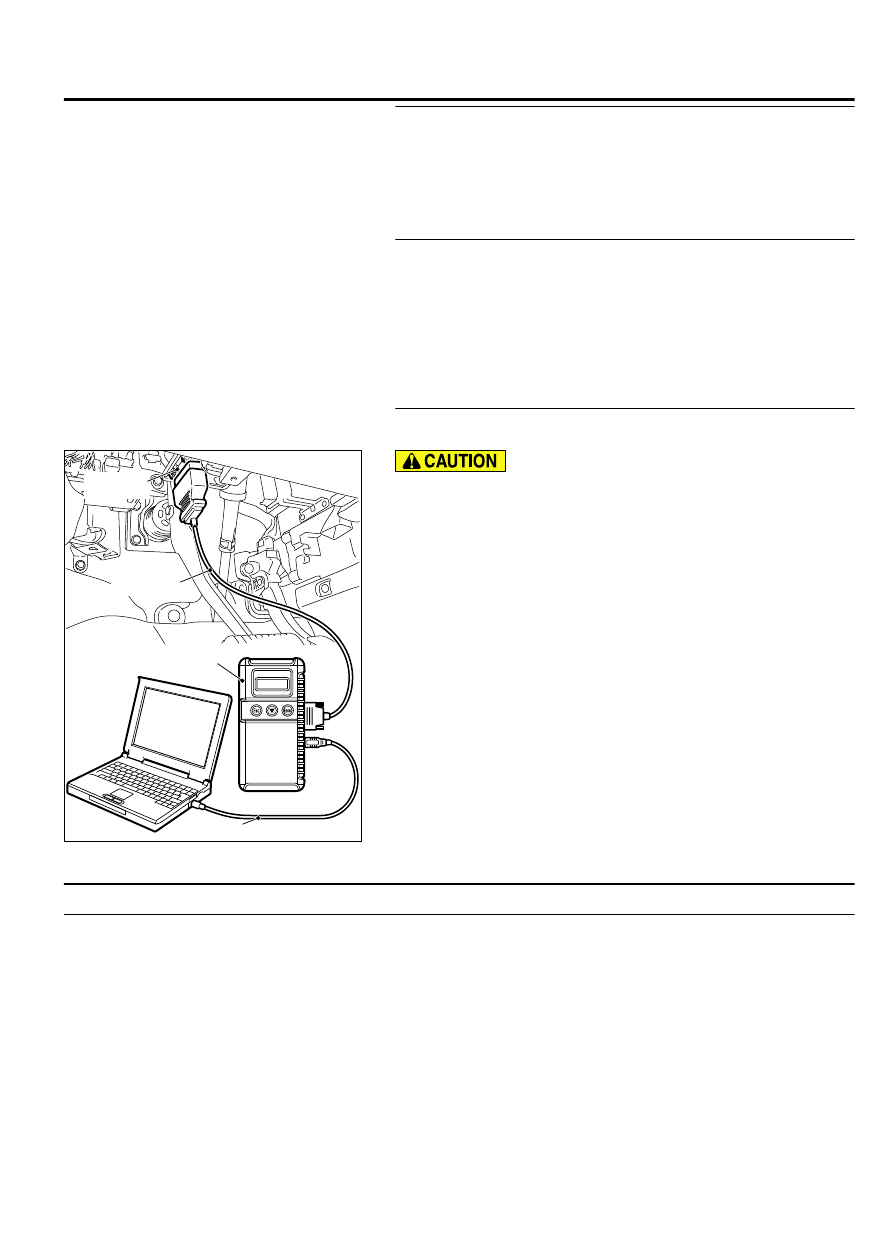
To prevent damage to scan tool MB991958, always turn the
ignition switch to the "LOCK" (OFF) position before
connecting or disconnecting scan tool MB991958.
(1)
Connect scan tool MB991958. Refer to "How to connect the
Scan Tool (M.U.T.-III) P.54Ab-5."
(2)
Turn the ignition switch to the "ON" position.
(3)
Erase the DTC.
(4)
Turn the ignition switch from "LOCK" (OFF) position to "ON"
position.
(5)
Check if DTC is set.
Q:Is the DTC set?
YES:
Go to Step 1.
NO:
The procedure is complete.
DTC B2465: Ignition switch signal error
M15410100048USA0000010000
TROUBLE JUDGMENT
If 5 seconds or more elapses with the ignition switch
state and the data from the CAN communication
contradicted, the combination meter stores the DTC
B2465.
TROUBLESHOOTING HINTS
⦆
The CAN bus line may be defective
⦆
The ETACS-ECU may be defective
⦆
The combination meter may be defective
COMBINATION METER
54Ab-21
DIAGNOSIS