Mitsubishi Outlander XL. Manual - part 946
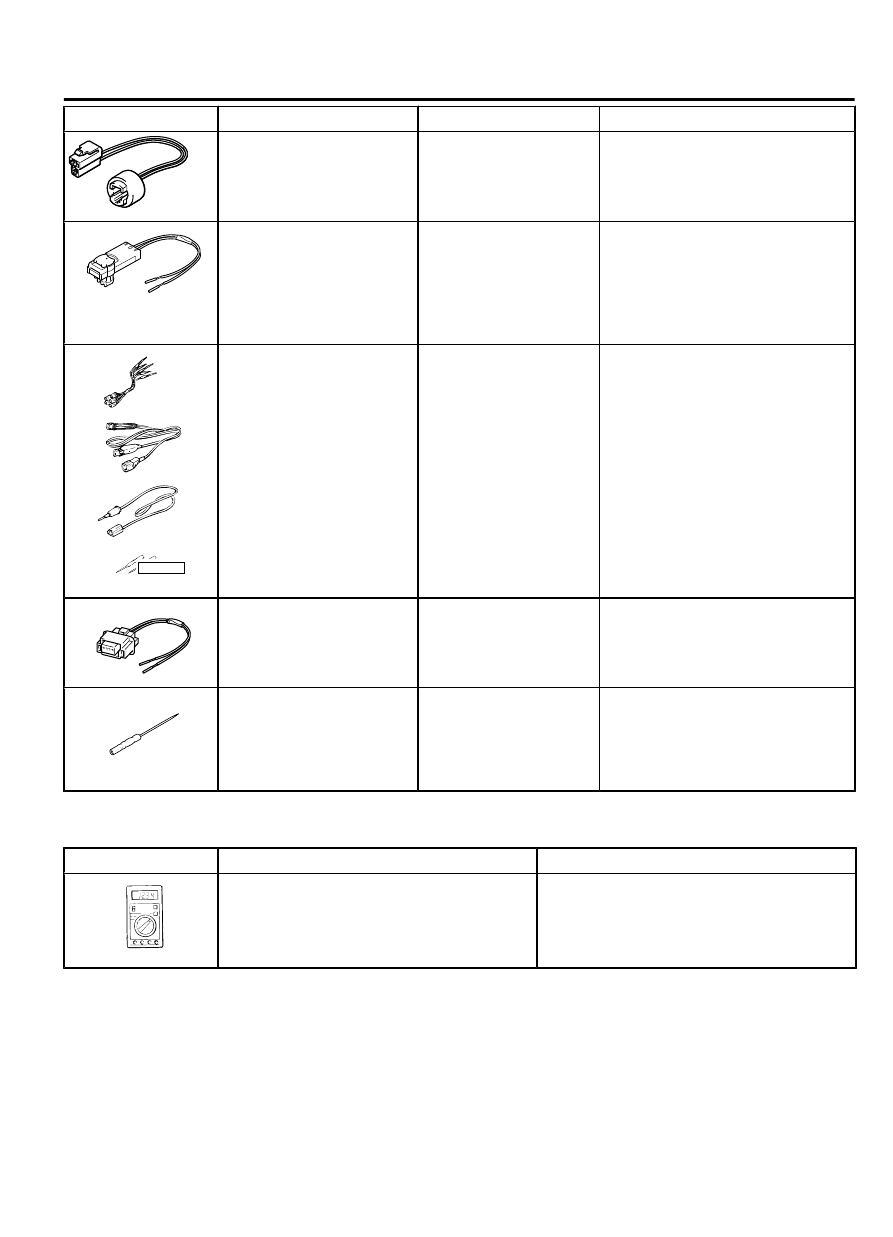
Tool
Tool number and name Supersession
Application
MB991884
MB991884
Resistor harness
⦆
Seat belt with pre-tensioner
circuit check
⦆
Curtain air bag circuit check
MB991885
MB991885
Adapter harness
⦆
Deployment of seat belt with
pre-tensioner and curtain air
bag inside the vehicle
⦆
Deployment of seat belt with
pre-tensioner and curtain air
bag outside the vehicle
YB9912230001
A
D
C
B
Do not use
MB991223
A: MB991219
B: MB991220
C: MB991221
D: MB991222
Harness set
A: Test harness
B: LED harness
C: LED harness adaptor
D: Probe
General service tools
Checking the continuity and
measuring the voltage at the SRS-
ECU harness connector
MB992102
MB992102
Air bag inflation adapter
harness
Deployment of driver’s or front
passenger’s (front) air bag inside
or outside the vehicle
MB992006
MB992006
Extra fine probe
Continuity check and voltage
measurement at harness wire or
connector for loose, corroded or
damaged terminals, or terminals
pushed back in the connector.
TEST EQUIPMENT
M15204000008USA0000010000
Tool
Name
Use
AC000019
Digital multi-meter
Use a multi-meter for which the maximum
test current is 2 mA or less at the minimum
range of resistance measurement
Checking the SRS electrical circuitry with
SRS check harness
POST-COLLISION DIAGNOSIS
M15204000011USA0000010000
To inspect and service the SRS after a collision (whether or not
the air bags have deployed), perform the following steps.
SUPPLEMENTAL RESTRAINT SYSTEM (SRS)
52B-315
TEST EQUIPMENT