Mitsubishi Outlander XL. Manual - part 944


  Index      Mitsubishi     Mitsubishi Outlander XL - service repair manual 2007 year


Search            copyright infringement  


Content   ..  942  943  944  945   ..


Mitsubishi Outlander XL. Manual - part 944


SYMPTOM PROCEDURES

INSPECTION PROCEDURE 1: Communication between the Scan Tool and the SRS-ECU
is not possible.

M15204000261USA0000010000
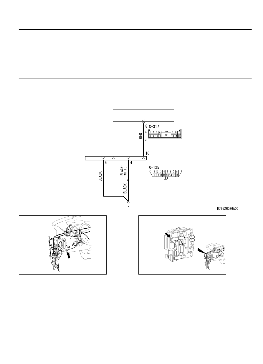
ETACS-ECU

Diagnosis Connector Circuit

FRONT SIDE

DATA LINK 
CONNECTOR

ZC6008750000

Connector: C-125

C-125 (B)

ZC6008780006

Connector: C-317


TECHNICAL DESCRIPTION (COMMENT)
If  the  scan  tool  (M.U.T.-III  Sub  Assembly)  can  not
communicate with the SRS system, the CAN bus lines
may be defective. If the SRS system does not work,
the  SRS-ECU  or  its  power  supply  circuit  may  be
defective.

TROUBLESHOOTING HINTS (The most likely
causes for this case:)

Damaged wiring harness or connector

Malfunction of the SRS-ECU

SUPPLEMENTAL RESTRAINT SYSTEM (SRS)

52B-307

SRS AIR BAG DIAGNOSIS

DIAGNOSIS

Required Special Tools:

MB991958: Scan Tool (M.U.T.-III Sub Assembly)

MB991824: Vehicle Communication Interface (V.C.I.)

MB991827: M.U.T.-III USB Cable

MB991910:  M.U.T.-III  Main  Harness  A  (Vehicles  with
CAN communication system)

STEP 1. V.C.I. status check
Check that the V.C.I. indicator light is illuminated in green.

Q:Is it illuminated in green?

YES:

 Diagnose the CAN bus line, and repair if necessary.

(Refer to GROUP 54D, Diagnosis P.54D-17.)

NO:

 Go to Step 2.

STEP 2. Connector check: C-317 ETACS-ECU connector,
C-125 data link connector

Q:Is the check result normal?

YES:

 Go to Step 3.

NO:

 Repair the connector concerned.

STEP 3. Wiring harness check between the C-317 ETACS-
ECU connector No. 8 and the C-125 data link connector
terminal No. 16

Check the power supply line for open circuit.

Q:Is the check result normal?

YES:

 Go to Step 4.

NO:

 Repair the wiring harness.

STEP 4. Wiring harness check between the C-125 data link
connector terminal No. 4 or 5 and the ground

Check the ground wires for open circuit.

Q:Is the check result normal?

YES:

 Check the scan tool.

NO:

 Repair the wiring harness.

52B-308

SUPPLEMENTAL RESTRAINT SYSTEM (SRS)

SRS AIR BAG DIAGNOSIS

INSPECTION PROCEDURE 2: Power supply circuit system

M15204000264USA0000010000

ETACS-ECU

SRS-ECU

IGNITION
SWITCH (IG1)

IG1  
RELAY

FUSIBLE
LINK

34

IG1 Power Supply Circuit

POWER 
SUPPLY

ZC600876

Connector: C-27

C-27 (Y)

0025

ZC6008780023

Connectors: C-309, C-313, C-317

C-309 (B)

C-316

C-317

SUPPLEMENTAL RESTRAINT SYSTEM (SRS)

52B-309

SRS AIR BAG DIAGNOSIS


CIRCUIT OPERATION

The SRS-ECU is energized by the ignition switch
(IG1) through multi-purpose fuse 18 and the SRS-
ECU terminal 61 and multi-purpose fuse 12 and the
SRS-ECU terminal 62.

If the power supply to the SRS-ECU has failed, scan
tool  (M.U.T.-III  Sub  Assembly)  will  not  be  able  to
communicate with it.

TROUBLESHOOTING HINTS (THE MOST LIKELY
CAUSES FOR THIS CASE:)

Damaged wiring harness or connector

Defective battery

Charging system failed

Malfunction of the SRS-ECU

DIAGNOSIS

Required Special Tools:

MB991958: Scan Tool (M.U.T.-III Sub Assembly)

MB991824: Vehicle Communication Interface (V.C.I.)

MB991827: M.U.T.-III USB Cable

MB991910:  M.U.T.-III  Main  Harness  A  (Vehicles  with
CAN communication system)

STEP 1. Resistance measurement at the C-27 SRS-ECU
connectors

ZC600210

A

Lock lever

0000

(1)

While  pushing  the  part  "A"  indicated  in  the  figure  of  the
harness side connector, turn the lock lever to the direction of
the arrow to release the lock lever, and disconnect the C-27
SRS-ECU connectors.


ZC5007880065

C-27 Harness side 
connector (front view)

(2)

Take the measurements below at the C-27 wiring harness
side connectors.

Continuity  between  C-27  wiring  harness  side  connector
terminal No. 59 and body ground

OK: Continuity (Less than 2 ohms)

Q:Is the check result normal?

YES:

 Go to Step 2.

NO:

 Repair the wiring harness between the C-27 SRS-ECU

connector terminal No. 59 and the ground.

STEP 2. Wiring harness check between the C-27 SRS-ECU
connector terminal Nos. 61 and 62 and the ignition switch
IG1

NOTE: 

Prior to the wiring harness inspection, check the

ETACS-ECU connectors C-309, C-317 and C-313, and repair if
necessary.

Check the power supply line for open circuit.

Q:Is the check result normal?

YES:

 Go to Step 3.

52B-310

SUPPLEMENTAL RESTRAINT SYSTEM (SRS)

SRS AIR BAG DIAGNOSIS


Content   ..  942  943  944  945   ..