Mitsubishi Outlander XL. Manual - part 898
ZC600210
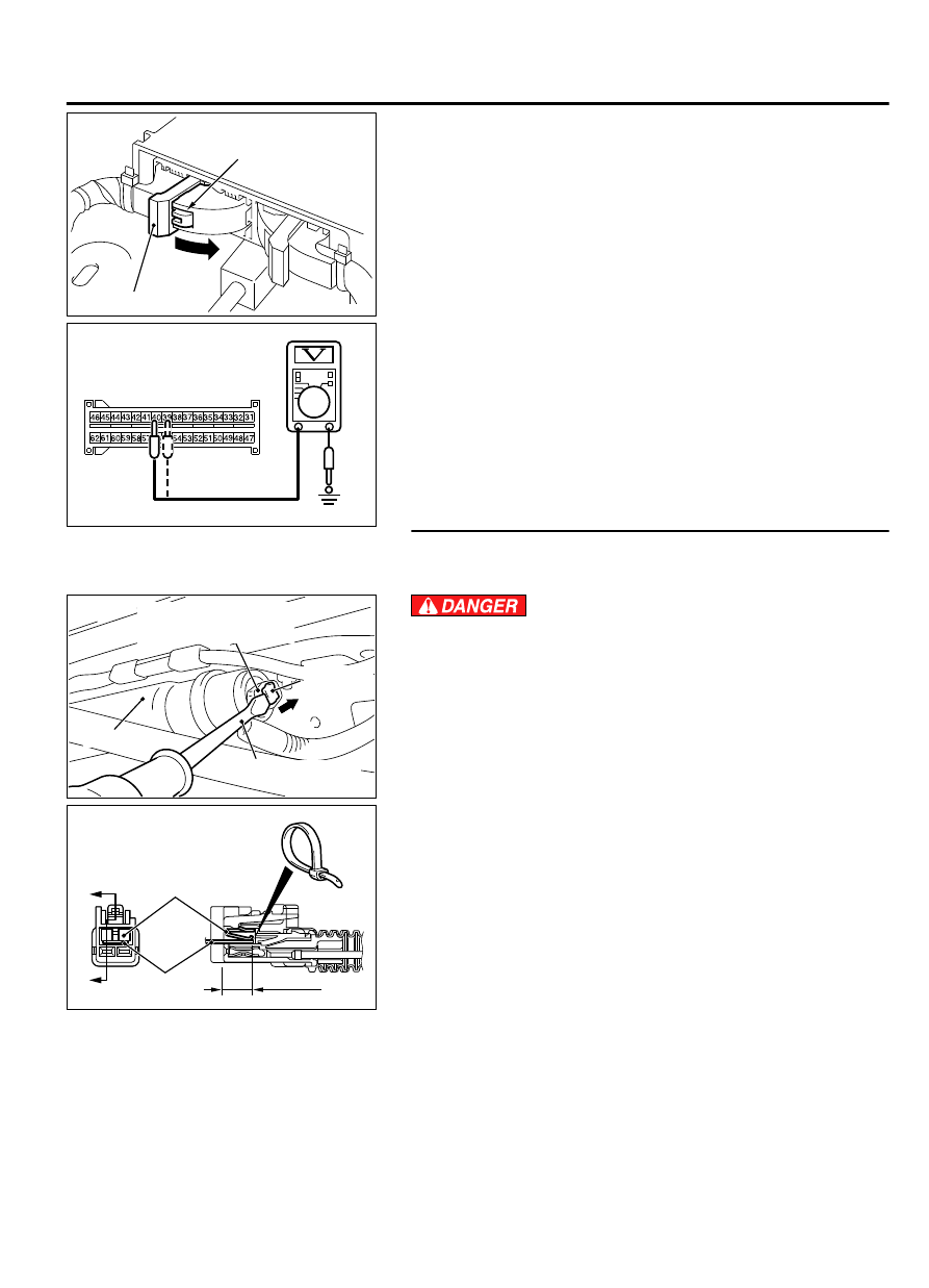
A
Lock lever
0000
(2)
While pushing the part "A" indicated in the figure of the
harness side connector, turn the lock lever to the direction of
the arrow to release the lock lever, and disconnect the C-27
SRS-ECU connector.
(3)
Disconnect the D-08 intermediate connector (connection
between curtain air bag harness and floor harness).
(4)
Connect the negative battery terminal.
(5)
Ignition switch: ON
ZC5007950016
C-27 Harness side
connector (front view)
(6)
Measure the voltage between the C-27 wiring harness side
connector terminal No. 39, 40 and body ground.
Voltage should measure 0 volt
Q:Is the measured 0 volt?
YES:
Go to Step 6.
NO:
Repair the wiring harness.
STEP 5. Voltage measurement at the D-08 intermediate
connector.
(1)
Disconnect the negative battery terminal.
ZC602163
Locking
button
Flat-tipped screwdriver
Inflator
Curtain air bag wiring
harness side connector
0000
To prevent the air bag from deploying unintentionally,
disconnect the curtain air bag module connector D-104 to
short the squib circuit.
(2)
Disconnect curtain air bag module (RH) D-104. Use a flat-
tipped screwdriver to unlock the locking button at the harness
side connector by withdrawing it toward you in two stages,
and then disconnect the connector.
(3)
Disconnect the D-08 intermediate connector (connection
between curtain air bag harness and floor harness).
ZC600212
D-08 Intermediate
connector (module side )
(front view)
A
A
4 mm or more
Terminal
Cable tie
Short
spring
Section
A - A
0001
(4)
Because the short spring is installed to the D-08 intermediate
connector (curtain air bag harness side), insert a cable tie [3
mm (0.12 inch) wide, 0.5 mm (0.02 inch) thick] between
terminals 1, 2 and the short spring to release the short spring.
(5)
Connect the negative battery terminal.
(6)
Ignition switch: ON
SUPPLEMENTAL RESTRAINT SYSTEM (SRS)
52B-123
SRS AIR BAG DIAGNOSIS