Mitsubishi Outlander XL. Manual - part 899


  Index      Mitsubishi     Mitsubishi Outlander XL - service repair manual 2007 year


Search            copyright infringement  


Content   ..  897  898  899  900   ..


Mitsubishi Outlander XL. Manual - part 899


STEP 2. Recheck for diagnostic trouble code.

ZC501967

AC404789

ZC5019680000

MB991824

MB991827

MB991910

Data link

connector

Check again if the DTC is set.

(1)

Erase the DTC.

(2)

Turn the ignition switch to "ON" position.

(3)

Check if the DTC is set.

(4)

Turn the ignition switch to the "LOCK" (OFF) position.

Q:Is the DTC set?

YES:

 Go to Step 3.

NO:

 There is an intermittent malfunction such as poor

engaged connector(s) or open circuit (Refer to GROUP 00,
How to Use Troubleshooting/Inspection Service Points -
How to Cope with Intermittent Malfunctions P.00-15).

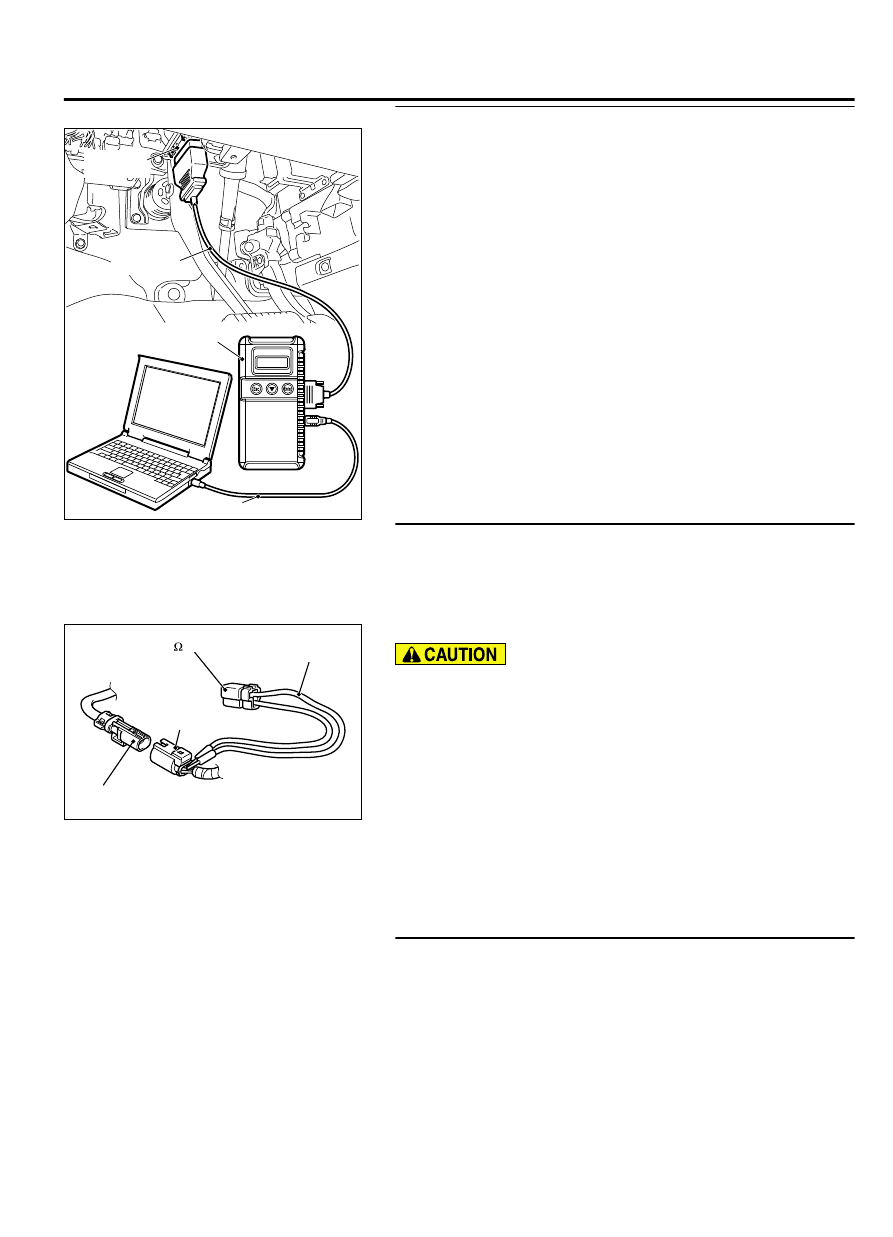
STEP 3. Check by dummy resistor connection. (Using scan
tool MB991958, read the diagnostic trouble code.)

(1)

Disconnect the negative battery terminal.

(2)

Disconnect  the  D-08  intermediate  connector  (connection
between curtain air bag harness and floor harness).

ZC600211

D-08 Intermediate connector 
(Curtain air bag harness side)

D-08 
Intermediate  
connector


(

Floor harness side

)

MB991865 
(Dummy resistor: 3 


)

MB991866  

(Resistor harness)

0001

(3)

Connect special tool MB991865 to special tool MB991866.

Do not insert a probe into the terminal from its front side
directly,  as  the  connector  contact  pressure  may  be
weakened.

(4)

Insert  the  probe  of  resistor  harness,  to  which  the  dummy
resistor  is  installed,  from  the  back  of  D-08  intermediate
connector (floor harness side).

(5)

Connect the negative battery terminal.

(6)

After erasing the diagnostic trouble code memory, check the
diagnostic trouble code again.

(7)

Disconnect the negative battery terminal.

Q:Is DTC B1B22 set?

YES:

 Go to Step 4.

NO:

 Go to Step 5.

STEP 4. Resistance measurement at the C-27 SRS-ECU
connector and the D-08 intermediate connector.

(1)

Disconnect the negative battery terminal.

SUPPLEMENTAL RESTRAINT SYSTEM (SRS)

52B-127

SRS AIR BAG DIAGNOSIS

ZC600210

A

Lock lever

0000

(2)

While  pushing  the  part  "A"  indicated  in  the  figure  of  the
harness side connector, turn the lock lever to the direction of
the arrow to release the lock lever, and disconnect the C-27
SRS-ECU connector.

(3)

Disconnect  the  D-08  intermediate  connector  (connection
between curtain air bag harness and floor harness).


ZC5007880029

D-08 Intermediate connector 
(Curtain air bag harness side)  
(rear view) 

C-27 Harness side 
connector (front view)

Do  not  insert  a  probe  into  the  terminal  from  D-08
intermediate connector front side directly, as the connector
contact pressure may be weakened.

(4)

Check  for  continuity  between  the  following  terminals.  It
should be less than 2 ohms.

SRS-ECU  connector  C-27  (terminal  No.39)  and  the
intermediate connector D-08 (terminal No.2)

SRS-ECU  connector  C-27  (terminal  No.40)  and  the
intermediate connector D-08 (terminal No.1)

Q:Does continuity exist?

YES:

 Go to Step 6.

NO:

 Repair the wiring harness between the C-27 harness

side connector terminal No. 39, 40 and the D-08
intermediate connector (floor harness side) terminal No.
2, 1.

STEP 5. Resistance measurement at the D-08 intermediate
connector terminal No. 1, 2 and the D-104 curtain air bag
module harness side connector terminal No. 1, 2.

(1)

Disconnect the negative battery terminal.

(2)

Disconnect  the  D-08  intermediate  connector  (connection
between curtain air bag harness and floor harness).

ZC602163

Locking  
button

Flat-tipped screwdriver

Inflator

Curtain air bag wiring  
harness side connector

0000

(3)

Disconnect curtain air bag module (RH) D-104. Use a flat-
tipped screwdriver to unlock the locking button at the harness
side connector by withdrawing it toward you in two stages,
and then disconnect the connector.

52B-128

SUPPLEMENTAL RESTRAINT SYSTEM (SRS)

SRS AIR BAG DIAGNOSIS

ZC603339

MB991884

D-104  
Harness side  
connector

0000

(4)

Connect  special  tool  MB991884  to  the  removed  D-104
harness side connector.

ZC5007880030

D-08 Intermediate connector 
(Curtain air bag harness side)  
(rear view) 

Resistor  

harness  

connector

Do  not  insert  a  probe  into  the  terminal  from  D-08
intermediate connector front side directly, as the connector
contact pressure may be weakened.

(5)

Check for continuity between the following terminals.
It should be less than 2 ohms.

Intermediate connector D-08 (terminal No.1) and resistor
harness connector terminal No.2)

Intermediate connector D-08 (terminal No.2) and resistor
harness connector terminal No.1)

Q:Is the check result normal?

YES:

 Replace the curtain air bag module (squib) (Refer

to P.52B-341).

NO:

 Repair the wiring harness.

STEP 6. Recheck for diagnostic trouble code.

ZC501967

AC404789

ZC5019680000

MB991824

MB991827

MB991910

Data link

connector

Check again if the DTC is set.

(1)

Erase the DTC.

(2)

Turn the ignition switch to the "ON" position.

(3)

Check if the DTC is set.

(4)

Turn the ignition switch to the "LOCK" (OFF) position.

Q:Is DTC B1B22 set?

YES:

 Replace SRS-ECU. (Refer to P.52B-326.)

NO:

 Intermittent Malfunction (Refer to GROUP 00, How to

Use Troubleshooting/Inspection Service Points - How to
Cope with Intermittent Malfunction P.00-15).

SUPPLEMENTAL RESTRAINT SYSTEM (SRS)

52B-129

SRS AIR BAG DIAGNOSIS

DTC B1B23: Curtain Air Bag Module (RH) (Squib) System (Short Circuit between Squib
Circuit Terminals)

M15204000958USA0000010000

: CONNECTOR LOCK SWITCH
  CONNECTOR COUPLED : ON
  CONNECTOR UNCOUPLED : OFF

NOTE

CURTAIN AIR BAG
MODULE
(SQUIB) (RH)

SRS-ECU

Curtain Air Bag Module (Squib) (RH) Circuit

ZC600876

Connector: C-27

C-27 (Y)

0025

ZC600880

Connectors: D-08, D-104

D-104 (B)

D-08 (Y)

0012

52B-130

SUPPLEMENTAL RESTRAINT SYSTEM (SRS)

SRS AIR BAG DIAGNOSIS


Content   ..  897  898  899  900   ..