Mitsubishi Outlander XL. Manual - part 896


  Index      Mitsubishi     Mitsubishi Outlander XL - service repair manual 2007 year


Search            copyright infringement  


Content   ..  894  895  896  897   ..


Mitsubishi Outlander XL. Manual - part 896


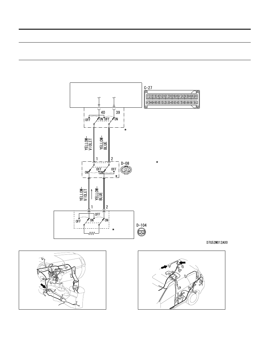
DTC B1B20: Curtain Air Bag Module (RH) (Squib) System (Shorted to Squib Circuit
Ground)

M15204000960USA0000010000

: CONNECTOR LOCK SWITCH
  CONNECTOR COUPLED : ON
  CONNECTOR UNCOUPLED : OFF

NOTE

CURTAIN AIR BAG
MODULE
(SQUIB) (RH)

SRS-ECU

Curtain Air Bag Module (Squib) (RH) Circuit

ZC600876

Connector: C-27

C-27 (Y)

0025

ZC600880

Connectors: D-08, D-104

D-104 (B)

D-08 (Y)

0012

SUPPLEMENTAL RESTRAINT SYSTEM (SRS)

52B-115

SRS AIR BAG DIAGNOSIS


If  DTC  B1B20  is  set  in  the  SRS-ECU,  always
diagnose the CAN main bus line.

CIRCUIT OPERATION

The SRS-ECU judges how severe a collision is by
detecting  signals  from  the  side  impact  sensors
installed on the lower side of the center pillar and at
the  quarter  panel  inner.  If  the  impact  is  over  a
predetermined  level,  the  SRS-ECU  sends  an
ignition signal. At this time, if the side-airbag safing
G-sensor is on, the SRS side-airbag will inflate.

The  ignition  signal  is  input  to  the  curtain  air  bag
module (RH) to inflate the curtain air bag.

DTC SET CONDITIONS
This  DTC  is  set  if  there  is  abnormal  resistance
between  the  input  terminals  of  the  curtain  air  bag
module (RH) (squib).

TROUBLESHOOTING HITS

Damaged wiring harnesses or connectors

Short to the ground in the curtain air bag module
(RH) (squib) harness

Malfunction of the SRS-ECU


DIAGNOSIS

Required Special Tools:

MB991958: Scan Tool (M.U.T.-III Sub Assembly)

MB991824: Vehicle Communication Interface (V.C.I.)

MB991827: M.U.T.-III USB Cable

MB991910:  M.U.T.-III  Main  Harness  A  (Vehicles  with
CAN Communication System)

MB991865: Dummy resistor

MB991866: Resister harness

STEP 1. Using scan tool MB991958, diagnose the CAN bus
line.

ZC501967

AC404789

ZC5019680000

MB991824

MB991827

MB991910

Data link

connector

To prevent damage to scan tool MB991958, always turn the
ignition  switch  to  the  "LOCK"  (OFF)  position  before
connecting or disconnecting scan tool MB991958.

(1)

Connect scan tool MB991958. Refer to "How to connect the
scan tool P.52B-31."

(2)

Turn the ignition switch to the "ON" position.

(3)

Diagnose the CAN bus line.

(4)

Turn the ignition switch to the "LOCK" (OFF) position.

Q:Is the CAN bus line found to be normal?

YES:

 Go to Step 2.

NO:

 Repair the CAN bus line (Refer to GROUP 54D,

Diagnosis P.54D-17).

52B-116

SUPPLEMENTAL RESTRAINT SYSTEM (SRS)

SRS AIR BAG DIAGNOSIS

STEP 2. Recheck for diagnostic trouble code.

ZC501967

AC404789

ZC5019680000

MB991824

MB991827

MB991910

Data link

connector

Check again if the DTC is set.

(1)

Erase the DTC.

(2)

Turn the ignition switch to "ON" position.

(3)

Check if the DTC is set.

(4)

Turn the ignition switch to the "LOCK" (OFF) position.

Q:Is the DTC set?

YES:

 Go to Step 3.

NO:

 There is an intermittent malfunction such as poor

engaged connector(s) or open circuit (Refer to GROUP 00,
How to Use Troubleshooting/Inspection Service Points -
How to Cope with Intermittent Malfunctions P.00-15).

STEP 3. Check by dummy resistor connection. (Using scan
tool MB991958, read the diagnostic trouble code.)

(1)

Disconnect the negative battery terminal.

(2)

Disconnect  the  D-08  intermediate  connector  (connection
between curtain air bag harness and floor harness).

ZC600211

D-08 Intermediate connector 
(Curtain air bag harness side)

D-08 
Intermediate  
connector


(

Floor harness side

)

MB991865 
(Dummy resistor: 3 


)

MB991866  

(Resistor harness)

0001

(3)

Connect special tool MB991865 to special tool MB991866.

Do not insert a probe into the terminal from its front side
directly,  as  the  connector  contact  pressure  may  be
weakened.

(4)

Insert  the  probe  of  resistor  harness,  to  which  the  dummy
resistor  is  installed,  from  the  back  of  D-08  intermediate
connector (floor harness side).

(5)

Connect the negative battery terminal.

(6)

After erasing the diagnostic trouble code memory, check the
diagnostic trouble code again.

(7)

Disconnect the negative battery terminal.

Q:Is DTC B1B20 set?

YES:

 Go to Step 4.

NO:

 Go to Step 5.

STEP 4. Resistance measurement at the C-27 SRS-ECU
connector

(1)

Disconnect the negative battery terminal.

SUPPLEMENTAL RESTRAINT SYSTEM (SRS)

52B-117

SRS AIR BAG DIAGNOSIS

ZC600210

A

Lock lever

0000

(2)

While  pushing  the  part  "A"  indicated  in  the  figure  of  the
harness side connector, turn the lock lever to the direction of
the arrow to release the lock lever, and disconnect the C-27
SRS-ECU connector.

(3)

Disconnect  the  D-08  intermediate  connector  (connection
between curtain air bag harness and floor harness).


ZC5007880027

C-27 Harness side 
connector (front view)

(4)

Check  for  continuity  between  C-27  wiring  harness  side
connector terminal No. 39, 40 and body ground.
It should be open circuit.

Q:Is the check result normal?

YES:

 Repair the wiring harness.

NO:

 Go to Step 5.

STEP 5. Resistance measurement at the D-08 intermediate
connector.

(1)

Disconnect the negative battery terminal.

ZC602163

Locking  
button

Flat-tipped screwdriver

Inflator

Curtain air bag wiring  
harness side connector

0000

To  prevent  the  air  bag  from  deploying  unintentionally,
disconnect the curtain air bag module connector D-104 to
short the squib circuit.

(2)

Disconnect curtain air bag module (RH) D-104. Use a flat-
tipped screwdriver to unlock the locking button at the harness
side connector by withdrawing it toward you in two stages,
and then disconnect the connector.

(3)

Disconnect  the  D-08  intermediate  connector  (connection
between curtain air bag harness and floor harness).

ZC600212

D-08 Intermediate  
connector (module side )  
(front view) 

A

A

4 mm or more

Terminal

Cable tie

Short 
spring

Section 
A - A

0001

(4)

Because the short spring is installed to the D-08 intermediate
connector (curtain air bag harness side), insert a cable tie [3
mm  (0.12  inch)  wide,  0.5  mm  (0.02  inch)  thick]  between
terminals 1, 2 and the short spring to release the short spring.

52B-118

SUPPLEMENTAL RESTRAINT SYSTEM (SRS)

SRS AIR BAG DIAGNOSIS


Content   ..  894  895  896  897   ..