Mitsubishi Outlander XL. Manual - part 877


  Index      Mitsubishi     Mitsubishi Outlander XL - service repair manual 2007 year


Search            copyright infringement  


Content   ..  875  876  877  878   ..


Mitsubishi Outlander XL. Manual - part 877


The  passenger’s  air  bag  OFF  indicator  light
illuminates when the ignition switch is turned to the
"ON"  position  and  goes  out  after  approximately
seven seconds if there is not a malfunction in the
SRS system.

If a failure occurs in the system, the SRS-ECU will
stop sending that SRS warning light "OFF" signal,
thus  causing  the  combination  meter  to  illuminate
the SRS warning light.

The SRS warning light "OFF" signal is not sent to
the combination meter in the cases below, either.
Therefore, the combination meter will illuminate the
SRS warning light.

The SRS-ECU connector is disconnected.

The SRS-ECU is not working normally due to a
failure in its power supply lines.

The  wiring  harness  between  the  passenger’s
air bag OFF indicator light and the SRS-ECU is
broken.

DTC SET CONDITIONS
This DTC will be set if an open circuit has occurred in
the wiring harness between the passenger’s air bag
OFF indicator light and the SRS-ECU.

TROUBLESHOOTING HINTS

Damaged wiring harnesses or connectors

Malfunction of the SRS-ECU

Malfunction  of  the  passenger’s  air  bag  OFF
indicator light

DIAGNOSIS

Required Special Tools:

MB991958: Scan Tool (M.U.T.-III Sub Assembly)

MB991824: Vehicle Communication Interface (V.C.I.)

MB991827: M.U.T.-III USB Cable

MB991910:  M.U.T.-III  Main  Harness  A  (Vehicles  with
CAN Communication System)

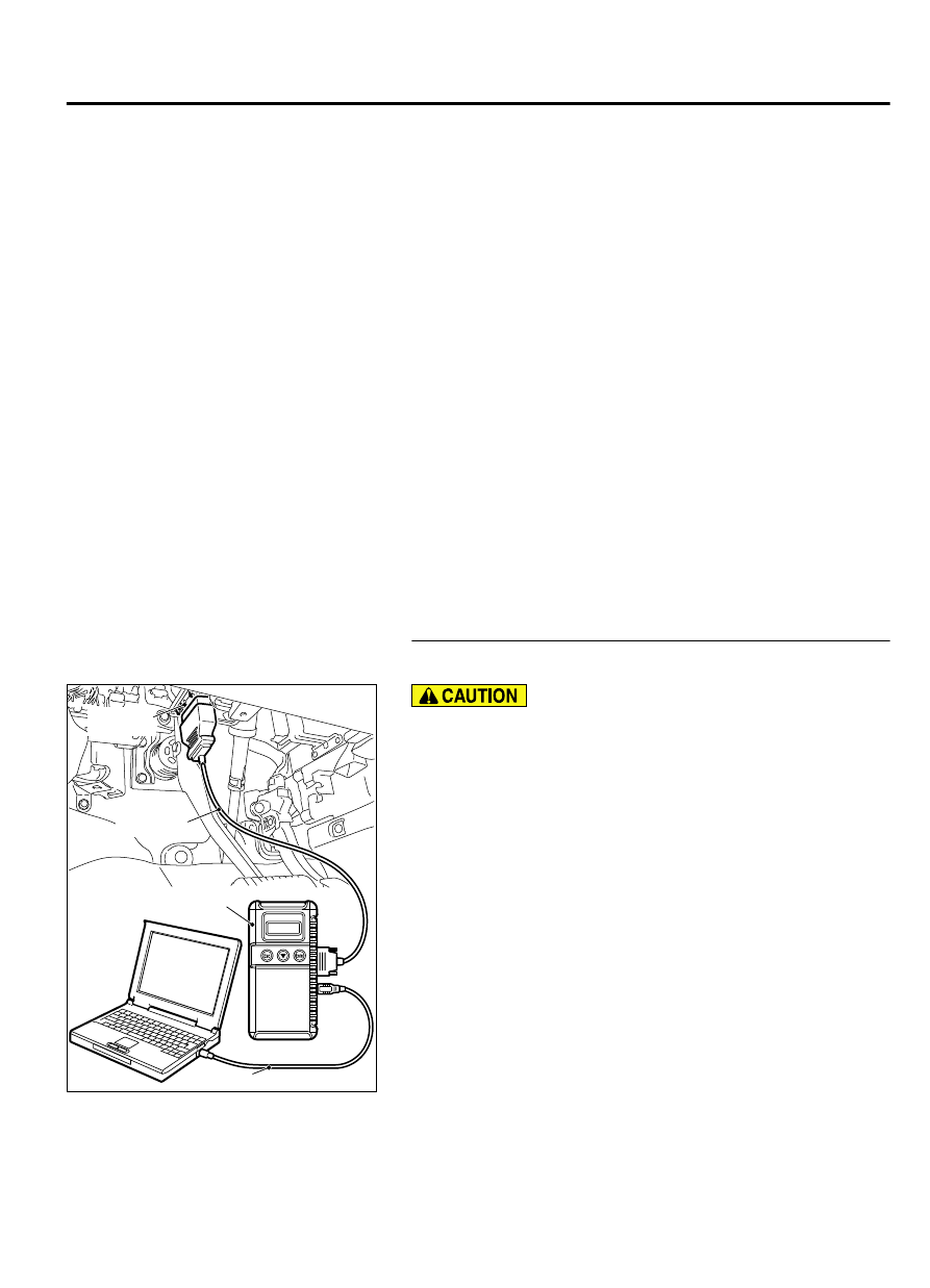
STEP 1. Using scan tool MB991958, diagnose the CAN bus
line.

ZC501967

AC404789

ZC5019680000

MB991824

MB991827

MB991910

Data link

connector

To prevent damage to scan tool MB991958, always turn the
ignition  switch  to  the  "LOCK"  (OFF)  position  before
connecting or disconnecting scan tool MB991958.

(1)

Connect scan tool MB991958. Refer to "How to connect the
scan tool P.52B-31."

(2)

Turn the ignition switch to the "ON" position.

(3)

Diagnose the CAN bus line.

(4)

Turn the ignition switch to the "LOCK" (OFF) position.

Q:Is the CAN bus line found to be normal?

YES:

 Go to Step 2.

NO:

 Repair the CAN bus line (Refer to GROUP 54D,

Diagnosis P.54D-17).

SUPPLEMENTAL RESTRAINT SYSTEM (SRS)

52B-39

SRS AIR BAG DIAGNOSIS

STEP 2. Recheck for diagnostic trouble code.

ZC501967

AC404789

ZC5019680000

MB991824

MB991827

MB991910

Data link

connector

Check again if the DTC is set.

(1)

Erase the DTC.

(2)

Turn the ignition switch to the "ON" position.

(3)

Check if the DTC is set.

(4)

Turn the ignition switch to the "LOCK" (OFF) position.

Q:Is the DTC set?

YES:

 Go to Step 3.

NO:

 There is an intermittent malfunction such as poor

engaged connector(s) or open circuit (Refer to GROUP 00,
How to Cope with Intermittent Malfunction P.00-15).

STEP 3. Using scan tool MB991958, read the diagnostic
trouble code.

ZC501967

AC404789

ZC5019680000

MB991824

MB991827

MB991910

Data link

connector

To prevent damage to scan tool MB991958, always turn the
ignition  switch  to  the  "LOCK"  (OFF)  position  before
connecting or disconnecting scan tool MB991958.

(1)

Turn the ignition switch to the "ON" position.

(2)

Check if the DTC is set.

(3)

Turn the ignition switch to the "LOOK (OFF)" position.

Q:Is  DTC  B1BAA,  B2207,  B2208,  B2209,  B220A,  B220B,

B220C, B220D or B2255 set?

YES:

 Carry out the troubleshooting of the occupant

classification-ECU or the occupant classification sensor
system. (Refer to B1BAA, B2207, B2208, B2209, B220A,
B220B, B220C, B220D or B2255).

NO:

 Go to Step 4.

STEP 4. Check the harness for open circuit between SRS-
ECU connector C-28 (terminal No.18) and the center panel
assembly connector C-104 (terminal No.11).

(1)

Disconnect SRS-ECU connector C-28.

52B-40

SUPPLEMENTAL RESTRAINT SYSTEM (SRS)

SRS AIR BAG DIAGNOSIS

ZC600210

A

Lock lever

0000

(2)

While  pushing  the  part  "A"  indicated  in  the  figure  of  the
harness side connector, turn the lock lever to the direction of
the arrow to release the lock lever, and disconnect the C-28
SRS-ECU connector.

(3)

Disconnect the center panel assembly connector C-104.

ZC500788

C-28 Harness side  
connector (front view)

C-104 
Harness side  
connector  
(front view)

0055

(4)

Check  for  continuity  between  the  following  terminals.  It
should be less than 2 ohms.

SRS-ECU connector C-28 (terminal No.18) and the center
panel assembly connector C-104 (terminal No.11)

Q:Does continuity exist?

YES:

 Erase the diagnostic trouble code memory, and check

the diagnostic trouble code. If DTC B1206 sets, replace
the SRS-ECU. (Refer to P.52B-326.) Then go to Step 5.

NO:

 Repair the harness wires. Then go to Step 5.

STEP 5. Recheck for diagnostic trouble code.

ZC501967

AC404789

ZC5019680000

MB991824

MB991827

MB991910

Data link

connector

Check again if the DTC is set.

(1)

Erase the DTC.

(2)

Turn the ignition switch to the "ON" position.

(3)

Check if the DTC is set.

(4)

Turn the ignition switch to the "LOCK" (OFF) position.

Q:Is DTC B1206 set?

YES:

 Return to Step 1.

NO:

 The procedure is complete.

SUPPLEMENTAL RESTRAINT SYSTEM (SRS)

52B-41

SRS AIR BAG DIAGNOSIS

DTC B1207: Passenger’s Air Bag OFF Indicator Light (Short Circuit between Circuit
Terminal)

M15204000993USA0000010000

CENTER PANEL ASSEMBLY

ETACS-ECU

INTERFACE
CIRCUIT

SRS-ECU

AIR BAG OFF 
INDICATOR 
LIGHT 
PASSENGER'S 
SIDE

Air Bag OFF Indicator Light Drive Circuit

ZC6008760000

Connector: C-28

C-28 (Y)

ZC6008760006

Connector: C-104

C-104


52B-42

SUPPLEMENTAL RESTRAINT SYSTEM (SRS)

SRS AIR BAG DIAGNOSIS


Content   ..  875  876  877  878   ..