Mitsubishi Outlander XL. Manual - part 854


  Index      Mitsubishi     Mitsubishi Outlander XL - service repair manual 2007 year


Search            copyright infringement  


Content   ..  852  853  854  855   ..


Mitsubishi Outlander XL. Manual - part 854


WINDSHIELD WIPER

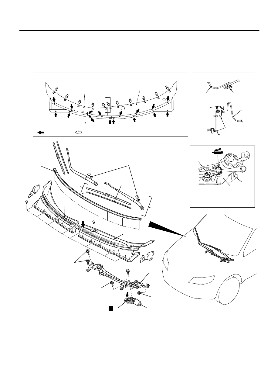
REMOVAL AND INSTALLATION

M15102100022USA0000010000

ZC5018660000

Section B – B

Section C – C

A

B

C

5

2

5

(LH)

5

(LH)

5

(RH)

5

(RH)

8

NOTE
        : Clip positions


: Claw positions

1

3

4

4

B

8

7

7

5

6

6

D

N

View D

Specified grease: Multipurpose 
grease SAE J310, NLGI No. 2 or 
equivalent

View A

Clip

Claw

8.0 ± 2.0 N·m
71 ± 18 in-lb

8.0 ± 2.0 N·m
71 ± 18 in-lb

8.0 ± 2.0 N·m
71 ± 18 in-lb

27 ± 3 N·m
20 ± 2 ft-lb

C

Wiper blade removal steps

1.

Wiper blade assembly

>>C<<

2.

Wiper blade

Windshield  wiper  motor  and  link
assembly removal steps

>>B<<

3.

Wiper arm and blade assembly

4.

Hood weatherstrip rear

WIPER AND WASHER

51B-49

WINDSHIELD WIPER

Windshield  wiper  motor  and  link
assembly removal steps

5.

Front deck garnish

6.

Windshield wiper link

7.

Wiper motor link plate

Windshield  wiper  motor  and  link
assembly removal steps

<<A>>

>>A<<

8.

Windshield wiper motor

Required Special Tool:

MB991955: M.U.T.-III sub-assembly

MB991223: Harness set

NOTE: 

For removal and installation of the wiper

and washer switch, refer to GROUP 54Ah, Column
switch P.54Ah-8.

REMOVAL SERVICE POINT

<<A>> WINDSHIELD WIPER MOTOR REMOVAL

ZC6002690001

Wiper motor 
link plate

1.

Remove the wiper link rod joint from the wiper motor link plate.

51B-50

WIPER AND WASHER

WINDSHIELD WIPER

ZC600270

4

5

3

1 2

4

5

3

1 2

0000

Wiper motor

<Link plate disconnected>

<Link plate rotated>

2.

Connect the wiper motor to a battery, and rotate the link plate
as shown.

3.

In  this  position,  withdraw  the  link  plate  from  the  wiper  link
assembly.

INSTALLATION SERVICE POINT

>>A<< WINDSHIELD WIPER MOTOR INSTALLATION

ZC6002760000

Wiper motor link plate

1.

Position the wiper motor link plate as shown, and assemble it
to the wiper link assembly.

NOTE:

The link plate can be assembled to the wiper link assembly
only at this position. If not, rotate the link plate to this position
(Refer to Stop Position Check, P.51B-53
).

Wiper  motor  replacement  parts  are  supplied  with  the  link
plate positioned as shown.

2.

Connect the assembled wiper motor to a battery, and set it to
the automatic stop position (Refer to Stop Position Check, P.
51B-53).

3.

Apply grease to the inside of link rod joint (as required) and
connect the link rod to wiper motor link plate.


WIPER AND WASHER

51B-51

WINDSHIELD WIPER

>>B<< WIPER ARM AND BLADE ASSEMBLY
INSTALLATION

ZC6002710000

A

A

A

A

Ø2(0.08) marking

Ø2(0.08) marking

5(0.20)

5(0.20)

Ø2(0.08) marking

Section A – A

Unit: mm(in)

Front deck garnish

Install  the  wiper  arm  and  blade  assembly  at  the  specified
positions.

(A): Φ 2(0.08 in) marking ± 5 mm(0.20 in)


>>C<< WIPER BLADE INSTALLATION

ZC6002720000

A

A

Wiper blade

Backing

Backing

Section A – A

Wiper
blade

Backing

Use a curved backing like that shown for the backing of a
wiper blade to ensure sustained wiper wiping performance.

51B-52

WIPER AND WASHER

WINDSHIELD WIPER


Content   ..  852  853  854  855   ..