Mitsubishi Outlander XL. Manual - part 829


  Index      Mitsubishi     Mitsubishi Outlander XL - service repair manual 2007 year


Search            copyright infringement  


Content   ..  827  828  829  830   ..


Mitsubishi Outlander XL. Manual - part 829


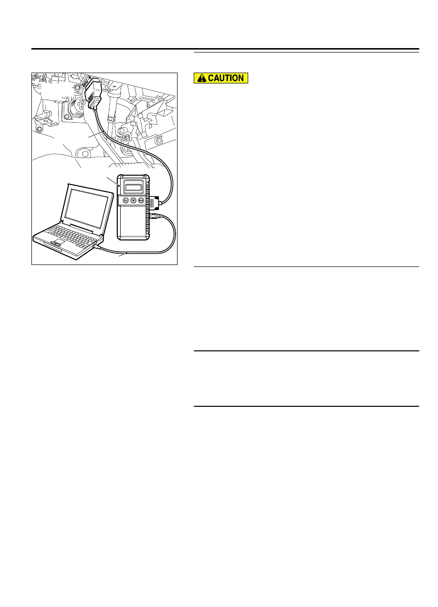
STEP 2. Using scan tool MB991958, read the diagnostic
trouble code.

ZC501967

AC404789

ZC5019680000

MB991824

MB991827

MB991910

Data link

connector

To prevent damage to scan tool MB991958, always turn the
ignition  switch  to  the  "LOCK"  (OFF)  position  before
connecting or disconnecting scan tool MB991958.

(1)

Connect scan tool MB991958. Refer to "How to connect scan
tool (M.U.T.-III) P.42C-7."

(2)

Turn the ignition switch to the "ON" position.

(3)

Check whether the ETACS-ECU related DTC is set.

(4)

Turn the ignition switch to the "LOCK" (OFF) position.

Q:Is the DTC set?

YES:

 Diagnose the ETACS-ECU. Refer to GROUP 54Ad, P.

54Ad-8.

NO:

 Go to Step 3.

STEP 3. Check the power supply system
With the ignition switch in the LOCK (OFF) position, check if the
following function operates normally:

Hazard warning light

Q:Is the check result normal?

YES:

 Go to Step 4.

NO:

 Refer to GROUP 54Ad, Malfunction of ETACS-ECU power

supply circuit P.54Ad-57.

STEP 4. Verify the central door locking system.

Q:Does the central door locking system work normally?

YES:

 Go to Step 5.

NO:

 Refer to GROUP 42Ab, Trouble Symptom Chart P.

42Ab-11.

STEP 5. Using scan tool MB991958, check data list.
Check the signals related to the keyless entry system operation.

WIRELESS CONTROL MODULE (WCM)

42C-75

DIAGNOSIS

ZC501967

AC404789

ZC5019680000

MB991824

MB991827

MB991910

Data link

connector

To prevent damage to scan tool MB991958, always turn the
ignition  switch  to  the  "LOCK"  (OFF)  position  before
connecting or disconnecting scan tool MB991958.

(1)

Connect scan tool MB991958. Refer to "How to connect the
Scan Tool (M.U.T.-III) P.42C-7."

(2)

Turn the ignition switch to the "ON" position.

(3)

Check the ETACS data list.

Turn the ignition switch to the LOCK (OFF) position.

Close the driver's door.

Close the passenger's door.

Close the RH-side rear door.

Close the LH-side rear door.

Close the liftgate.

Remove the ignition key from the ignition key cylinder.

Item No.

Item name

Normal
condition

Item 254

IG voltage

Battery
voltage

Item 256

Dr door ajar switch

Close

Item 257

As door ajar switch

Close

Item 258

RR door ajar switch Close

Item 259

RL door ajar switch

Close

Item 260

Trunk/gate trunk ajar
switch

Close

Item 264

Handle lock switch

Key in → Key
out

(4)

Turn the ignition switch to the "LOCK" (OFF) position.

OK: Normal condition is displayed.

Q:Is the check result normal?

YES (Normal conditions are displayed for all the items.):

Go to Step 6.

NO (Normal condition is not displayed for item No.
254.):

 Refer to GROUP 54Ad, Inspection Procedure 2: ETACS-

ECU does not receive any signal from the ignition switch
(IG1) P.54Ad-62.

NO (Normal condition is not displayed for item No.
256.):

 Refer to GROUP 54Ad, Inspection Procedure 5: ETACS-

ECU does not receive any signal from the front door switch
(LH) P.54Ad-73.

NO (Normal condition is not displayed for item No.
257.):

 Refer to GROUP 54Ad, Inspection Procedure 6: ETACS-

ECU does not receive any signal from the front door switch
(RH) P.54Ad-75.

NO (Normal condition is not displayed for item No.
258.):

 Refer to GROUP 54Ad, Inspection Procedure 8: ETACS-

ECU does not receive any signal from the rear door switch
(RH) P.54Ad-80.

42C-76

WIRELESS CONTROL MODULE (WCM)

DIAGNOSIS

NO (Normal condition is not displayed for item No.
259.):

 Refer to GROUP 54Ad, Inspection Procedure 7: ETACS-

ECU does not receive any signal from the rear door switch
(LH) P.54Ad-77.

NO (Normal condition is not displayed for item No.
260.):

 Refer to GROUP 54Ad, Inspection Procedure 9: ETACS-

ECU does not receive any signal from the liftgate
switch P.54Ad-82.

NO (Normal condition is not displayed for item No.
264.):

 Refer to GROUP 54Ad, Inspection Procedure 3: ETACS-

ECU does not receive any signal from the key reminder
switch. P.54Ad-64.

STEP 6. Using scan tool MB991958, check pulse check.
Check the signals related to the keyless entry system operation.

ZC501967

AC404789

ZC5019680000

MB991824

MB991827

MB991910

Data link

connector

To prevent damage to scan tool MB991958, always turn the
ignition  switch  to  the  "LOCK"  (OFF)  position  before
connecting or disconnecting scan tool MB991958.

(1)

Connect scan tool MB991958. Refer to "How to connect the
Scan Tool (M.U.T.-III) P.42C-7."

(2)

Confirm the ETACS pulse check.

Remove the ignition key from the ignition key cylinder.

Item name

Conditions

Transmitter switch

Turn the switch ON/OFF.


OK: The scan tool (M.U.T.-III) tone alarm sounds.

Q:Is the check result normal?

YES:

 Go to Step 7.

NO:

 Refer to P.42C-80.

STEP 7. Retest the system.
Check if the keyless entry system works normally.

Q:Is the check result normal?

YES:

 Intermittent malfunction (Refer to GROUP 00 - How

to Use Troubleshooting/Inspection Service Points - How to
Cope with Intermittent Malfunction P.00-15).

NO:

 Replace WCM and register the ID codes (Refer to P.

42C-85).

WIRELESS CONTROL MODULE (WCM)

42C-77

DIAGNOSIS

INSPECTION PROCEDURE 6: The Dome Light, The Turn-signal Lights The Horn do not
Operate through The Answerback Function.

M14209200040USA0000010000

Before  replacing  the  ECU,  ensure  that  the  power  supply
circuit, the ground circuit and the communication circuit are
normal.

COMMENTS ON TROUBLE SYMPTOM
If  the  hazard  warning  light,  the  dome  light  and  the  horn  work
normally,  ETACS-ECU  may  be  faulty.  Also,  the  answerback
function  may  have  been  disabled  using  the  customization
function.

PROBABLE CAUSES

Malfunction of the turn signal light

Malfunction of the dome light

Malfunction of the horn

Malfunction of ETACS-ECU

Damaged wiring harness and connectors

DIAGNOSTIC PROCEDURE

STEP 1. Verify the hazard warning lights.
Check that the hazard warning lights illuminate normally.

Q:Is the check result normal?

YES:

 Go to Step 2.

NO:

 Refer to GROUP 54Ac, Inspection Procedure 1: The

Hazard Warning lights do not Illuminate P.54Ac-163.

STEP 2. Verify the dome light.
Check that the dome light illuminate normally.

Q:Is the check result normal?

YES:

 Go to Step 3.

NO:

 Refer to GROUP 54Ac, Trouble Symptom Chart P.

54Ac-140.

STEP 3. Verify the horn.
Check that the horn normally.

Q:Is the check result normal?

YES:

 Go to Step 4.

NO:

 Replace the horn (Refer to GROUP 54Af, Horn P.

54Af-28).

STEP 4. Check the operation of the keyless entry system.
Operate the transmitter and check that all doors (including the
liftgate) lock and unlock.

Q:Is the check result normal?

42C-78

WIRELESS CONTROL MODULE (WCM)

DIAGNOSIS


Content   ..  827  828  829  830   ..