Mitsubishi Outlander XL. Manual - part 827
DIAGNOSIS
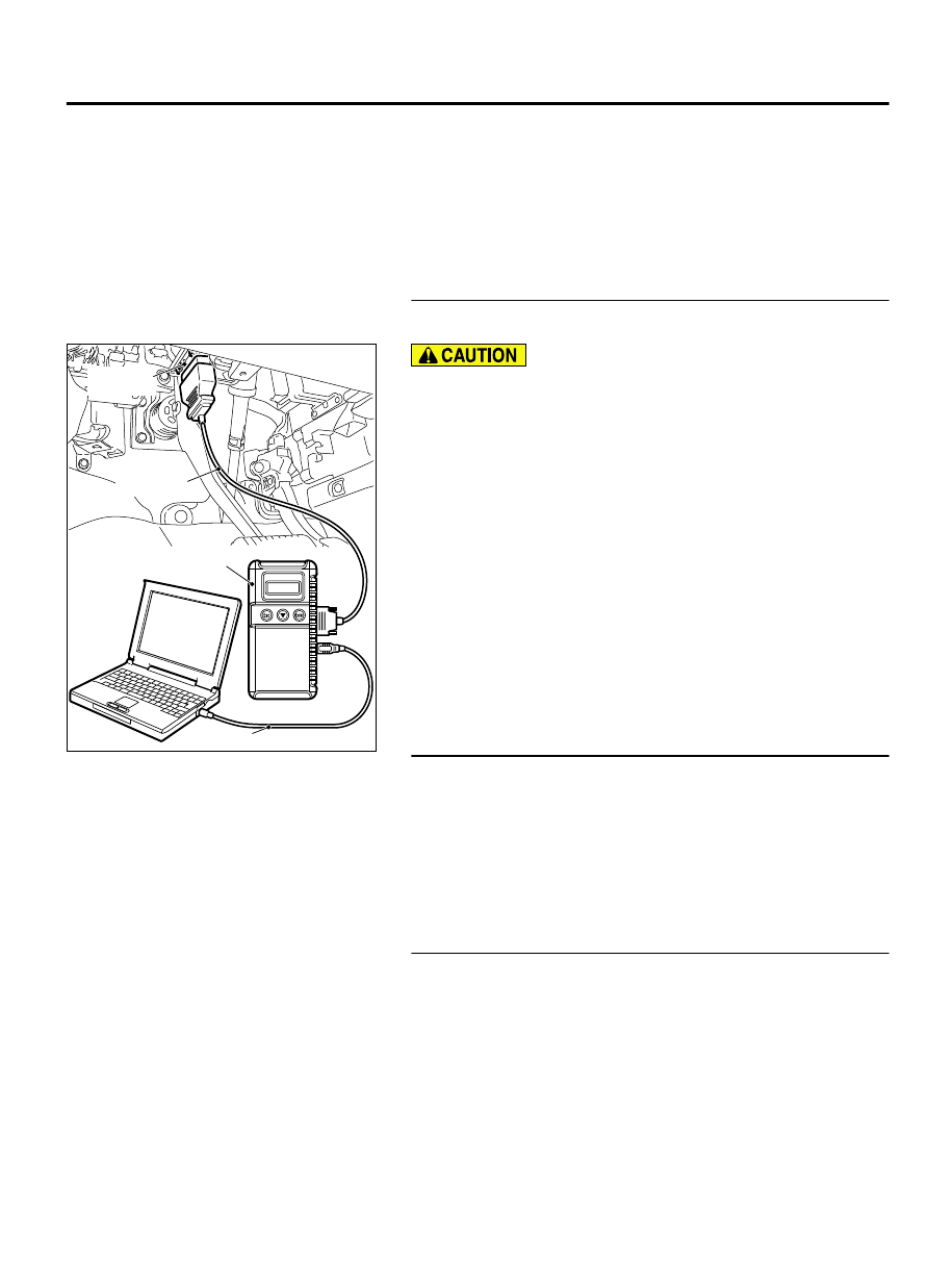
Required Special Tools:
⦆
MB991958: Scan Tool (M.U.T.-III Sub Assembly)
⦆
MB991824: Vehicle Communication Interface (V.C.I.)
⦆
MB991827: M.U.T.-III USB Cable
⦆
MB991910: M.U.T.-III Main Harness A (Vehicles with
CAN communication system)
STEP 1. Using scan tool MB991958, diagnose the CAN bus
line.
ZC501967
AC404789
ZC5019680000
MB991824
MB991827
MB991910
Data link
connector
To prevent damage to scan tool MB991958, always turn the
ignition switch to the "LOCK" (OFF) position before
connecting or disconnecting scan tool MB991958.
(1)
Connect scan tool MB991958. Refer to "How to connect the
Scan Tool (M.U.T.-III) P.42C-7."
(2)
Turn the ignition switch to the "ON" position.
(3)
Diagnose the CAN bus line.
(4)
Turn the ignition switch to the "LOCK" (OFF) position.
Q:Is the CAN bus line found to be normal?
YES:
Go to Step 2.
NO:
Repair the CAN bus line. (Refer to GROUP 54D,
STEP 2. Check the power supply circuit and the ground
circuit to WCM.
Refer to INSPECTION PROCEDURE 4 "Check WCM Power
Supply/Ground Circuits" P.42C-71.
Q:Is the power supply circuit and the ground circuit to WCM
in good condition ?
YES:
Go to Step 3.
NO:
Repair the power supply circuit and the ground
circuit to WCM.
STEP 3. Retest the system
Check if scan tool can communicate with WCM.
Q:Does the scan tool cannot communicate with WCM in
good condition?
YES:
The trouble can be an intermittent malfunction
(Refer to GROUP 00 - How to use Troubleshooting/
inspection Service Points - How to Cope with Intermittent
Malfunction P.00-15).
NO:
Replace WCM and register the ID codes. (Refer to P.
WIRELESS CONTROL MODULE (WCM)
42C-67
DIAGNOSIS