Mitsubishi Outlander XL. Manual - part 828


  Index      Mitsubishi     Mitsubishi Outlander XL - service repair manual 2007 year


Search            copyright infringement  


Content   ..  826  827  828  829   ..


Mitsubishi Outlander XL. Manual - part 828


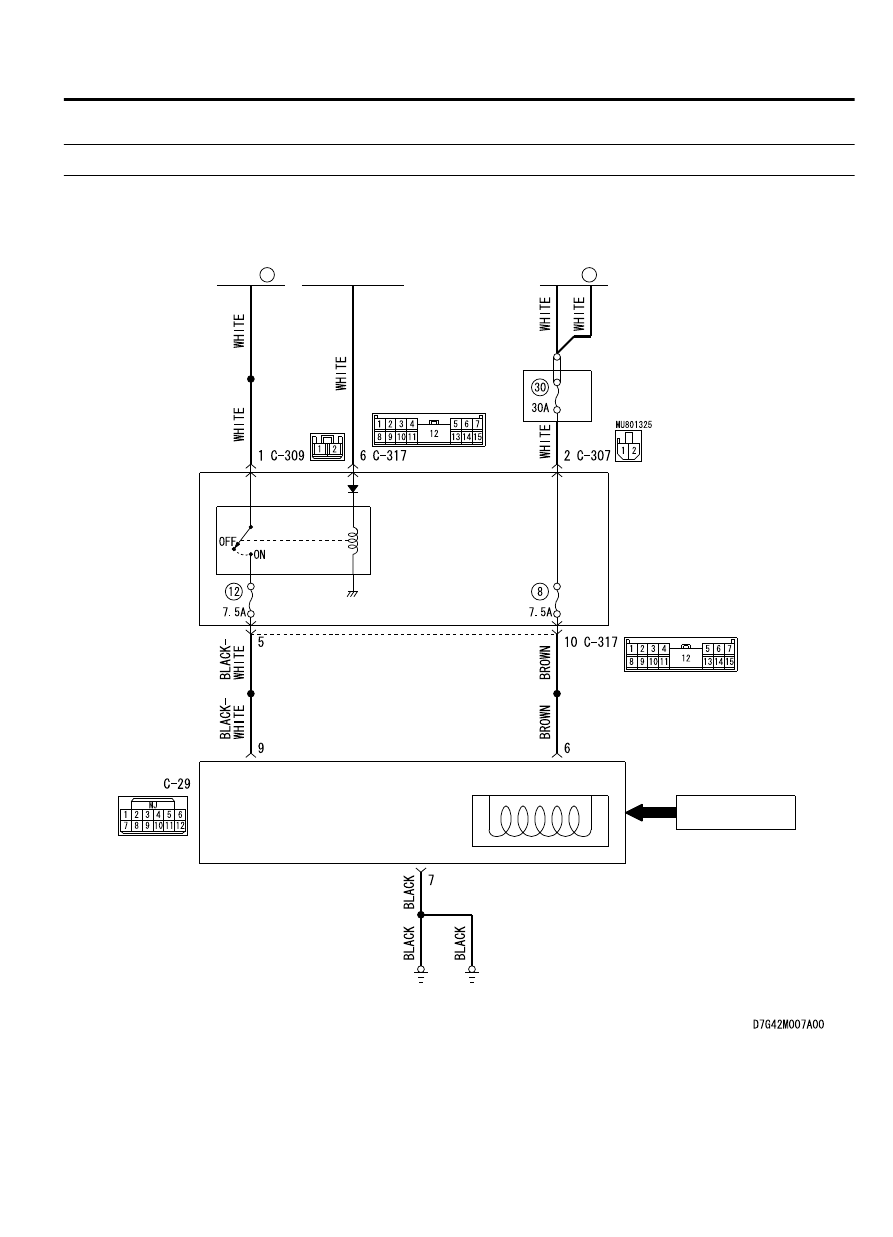
Inspection Procedure 4: Check the WCM power supply and ground circuits.

M14209200038USA0000010000

WCM Power Supply Circuit

34

FUSIBLE
LINK

36

FUSIBLE
LINK

IGNITION
SWITCH (IG1)

ETACS-
ECU

IGNITION KEY
RING ANTENNA

ENCRYPTED CODE

TRANSPONDER

IG1
RELAY

RELAY 
BOX 

WCM

WIRELESS CONTROL MODULE (WCM)

42C-71

DIAGNOSIS

ZC6008750033

Connector: C-29

ZC6008780029

Connectors: C-307, C-309, C-317

C-307 (B)

C-309 (B)

C-317

DIAGNOSIS

Required Special Tools:

MB992006: Extra fine probe

MB991223: Harness set

STEP 1. Check WCM connector C-29 for loose, corroded or
damaged terminals, or terminals pushed back in the
connector.

Q:Is the WCM connector C-29 in good condition?

YES:

 Go to Step 2.

NO:

 Repair the defective connector.

STEP 2. Check the battery power supply circuit to the WCM.
Measure the voltage at WCM connector C-29.

(1)

Disconnect WCM connector C-29 and measure the voltage
available at the harness side of the connector.

(2)

Turn the ignition switch to the ON position.

ZC5010400055

Harness side: C-29

(3)

Measure the voltage between terminal No. 6 or 9 and ground.

The  voltage  should  measure  approximately  12  volts
(battery positive voltage).

Q:Is the measured voltage approximately 12 volts (battery

positive voltage)?

YES:

 Go to Step 4.

NO:

 Go to Step 3.

42C-72

WIRELESS CONTROL MODULE (WCM)

DIAGNOSIS

STEP 3. Check the wiring harness between WCM connector
C-29 (terminal No. 9, 6) and fusible link (36, 34).

NOTE: 

Before checking the wiring harnesses, check the

ETACS-ECU connectors C-307, C-309, and C-317, and repair if
necessary.

Check the power supply line for open circuit.

Q:Is  the  wiring  harness  between  WCM  connector  C-29

(terminal  No.  9,  6)  and  fusible  link  (36,  34)  in  good

condition?

YES:

 Go to Step 4.

NO:

 The wiring harness may be damaged or the connector

(s) may have loose, corroded or damaged terminals, or
terminals pushed back in the connector. Repair the wiring
harness as necessary. Verify that the high-beam
headlights illuminate normally.

STEP 4. Check the ground circuit to the WCM. Measure the
resistance at WCM connector C-29.

(1)

Disconnect the connector and measure the resistance at the
wiring harness side.

(2)

Turn the ignition switch to the ON position.

ZC5010410051

Harness side: C-29

(3)

Measure  the  resistance  between  terminal  No.  7  and  the
ground.

The resistance should be 2 Ω or less.

Q:Is the measured resistance 2 Ω or less?

YES:

 The procedure is complete.

NO:

 Go to Step 5.

STEP 5. Check the wiring harness between the WCM
connector C-29 ( terminal No. 7) and the ground.

Check the ground wires for open circuit.

Q:Is  the  wiring  harness  between  WCM  connector  C-29

( terminal No. 7) and the ground in good condition?

YES:

 The procedure is complete.

NO:

 The wiring harness may be damaged or the connector

(s) may have loose, corroded or damaged terminals, or
terminals pushed back in the connector. Repair the wiring
harness as necessary. Verify that the high-beam
headlights illuminate normally.

INSPECTION PROCEDURE 5: Keyless Entry System does not Work.

M14209200039USA0000010000

Before  replacing  the  ECU,  ensure  that  the  power  supply
circuit, the ground circuit and the communication circuit are
normal.

WIRELESS CONTROL MODULE (WCM)

42C-73

DIAGNOSIS

OPERATION
The  lock/unlock  signals  from  the  transmitter  are  received  by
WCM, and then sent to ETACS-ECU from WCM. When ETACS-
ECU receives signals from the key reminder switch and all the
door switches, ETACS-ECU actuates the keyless entry system.

PROBABLE CAUSES

Malfunction of the key reminder switch

Malfunction of the door switches

Malfunction of keyless entry transmitter

Malfunction of the WCM

Malfunction of ETACS-ECU

Damaged wiring harness and connectors

Option coding information

DIAGNOSTIC PROCEDURE

Required Special Tools:

MB991223: Harness Set

MB992006: Extra Fine Probe

MB991958: Scan Tool (M.U.T.-III Sub Assembly)

MB991824: V.C.I.

MB991827: M.U.T.-III USB Cable

MB991910: M.U.T.-III Main Harness A

STEP 1. Scan tool (M.U.T.-III) CAN bus diagnostics
Use  scan  tool  MB991958  (M.U.T.-III),  diagnose  the  CAN  bus
lines.

Q:Is the CAN bus normal?

YES:

 Go to Step 2.

NO:

 Repair the CAN bus line (Refer to GROUP 54D, CAN bus

diagnostics chart P.54D-17).

42C-74

WIRELESS CONTROL MODULE (WCM)

DIAGNOSIS


Content   ..  826  827  828  829   ..