Mitsubishi Outlander XL. Manual - part 800


  Index      Mitsubishi     Mitsubishi Outlander XL - service repair manual 2007 year


Search            copyright infringement  


Content   ..  798  799  800  801   ..


Mitsubishi Outlander XL. Manual - part 800


terminals pushed back in the connector. Repair the wiring
harness as necessary. Check that the liftgate lock
release handle works normally.

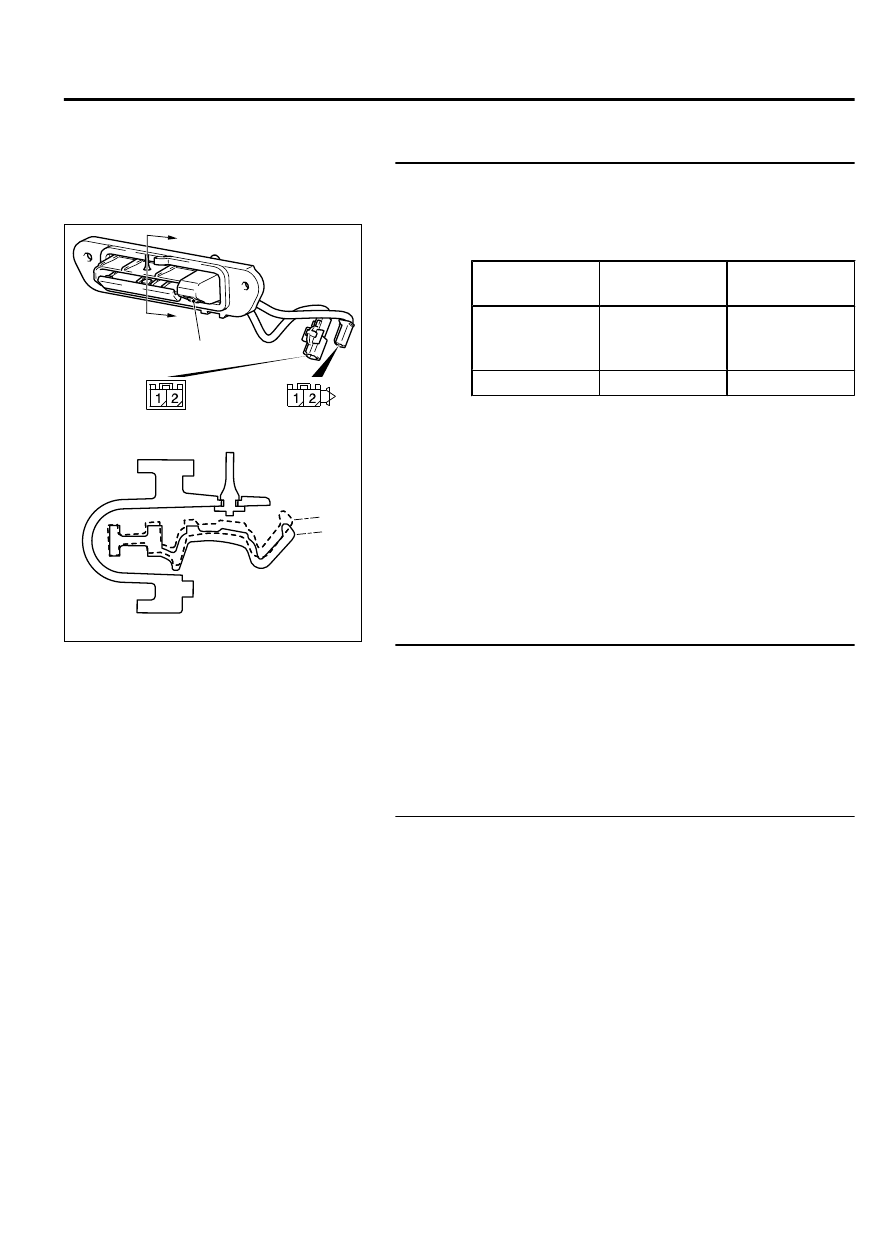
STEP 4. Liftgate lock release handle check

(1)

Remove the liftgate lock release handle (Refer to GROUP
42Ac, Liftgate Handle and Latch P.42Ac-10).

ZC6001180000

A

A

ON

OFF

Section A – A

Liftgate lock
release handle

Lock switch

Lock switch

(2)

Check  continuity  when  the  liftgate  lock  release  handle  is
operated to "ON" or "OFF" position.

Switch
position

Terminal
number

Normal value

ON

1 - 2

Continuity
exists  (2  Ω  or
less)

OFF

1 - 2

Open circuit

Q:Is the liftgate lock release handle normal?

YES:

 Go to Step 5.

NO:

 Replace the liftgate lock release handle. Check that

the liftgate lock release handle works normally.

STEP 5. KOS communication test
Using scan tool (M.U.T-III), perform the antenna communication
test to check that the exterior transmitter antenna (liftgate side)
is normal (Refer to P.42B-169).

Q:Is the check result normal?

YES:

 Go to Step 6.

NO:

 Perform troubleshooting for the diagnostic trouble

code No. B240C (Refer to P.42B-18).

STEP 6. Check of the troubles
Operate the liftgate lock release handle to check that the door
can be locked.

Q:Is the check result normal?

YES:

 Intermittent malfunction is suspected. (Refer to

GROUP 00, How to Use Troubleshooting/Inspection Service
Points - How to cope with intermittent malfunctions P.
00-15).

NO:

 Replace KOS-ECU and register the ID codes (Refer

to P.42B-163).

KEYLESS OPERATION SYSTEM (KOS)

42B-143

DIAGNOSIS

INSPECTION PROCEDURE 13: KEYLESS ENTRY SYSTEM DOES NOT WORK.

M14209100079USA0000010000

Before replacing the ECU, ensure that the power
supply  circuit,  the  ground  circuit  and  the
communication circuit are normal.

42B-144

KEYLESS OPERATION SYSTEM (KOS)

DIAGNOSIS

ZC603134

FUSIBLE
LINK

36

RELAY 
BOX

KEY
REMINDER
SWITCH

WHEN 
REMOVING 
KEY: ON

ETACS-ECU

PUSH 
SWITCH

RECEIVER ANTENNA MODULE

KEYLESS 
ENTRY 
RECEIVER

KOS-ECU

KEYLESS
OPERATION
KEY

ENCRYPTED CODE

TRANSPONDER

BLA

CK

BLA

CK

BLA

CK

BLA

CK

BLA

CK

BLA

CK

BLA

CK

WHITE

BR

O

WN

BR

O

WN

WHITE

WHITE

RED-WHITE

RED-GREEN

RED- WHITE

RED

WHITE-BLA

CK

YELLO

W

-BLA

CK

YELLO

W

-VIOLET

VIOLET

GREEN

PINK

BR

O

WN

-WHITE

0000

KOS-ECU System Circuit

KEYLESS OPERATION SYSTEM (KOS)

42B-145

DIAGNOSIS

ZC600875

C-102

C-30

0029

Connectors: C-30, C-102

ZC6008770002

Connector: C-211

ZC600878

Connectors: C-307, C-315, 317

0021

C-315

C-317

C-307 (B)

OPERATION
The  receiver  antenna  module  receives  lock  and
unlock  signals  from  the  keyless  operation  key,  and
sends them to KOS-ECU, and further to ETACS-ECU.
Also,  when  ETACS  receives  signals  from  the  key
reminder  switch  and  all  the  door  switches,  ETACS-
ECU  judges  them  to  activate  the  keyless  entry
system.

PROBABLE CAUSES

Malfunction of CAN bus line

Malfunction of the door switches

Malfunction of the key reminder switch

Malfunction of the receiver antenna module

Malfunction of the keyless operation key

Damaged wiring harness and connectors

Malfunction of the KOS-ECU

Malfunction of ETACS-ECU

DIAGNOSTIC PROCEDURE

Required Special Tools:

MB991223: Harness Set

MB992006: Extra Fine Probe

MB991958: Scan Tool (M.U.T.-III Sub Assembly)

MB991824: V.C.I.

MB991827: M.U.T.-III USB Cable

MB991910: M.U.T.-III Main Harness A

42B-146

KEYLESS OPERATION SYSTEM (KOS)

DIAGNOSIS


Content   ..  798  799  800  801   ..