Mitsubishi Outlander XL. Manual - part 791


  Index      Mitsubishi     Mitsubishi Outlander XL - service repair manual 2007 year


Search            copyright infringement  


Content   ..  789  790  791  792   ..


Mitsubishi Outlander XL. Manual - part 791


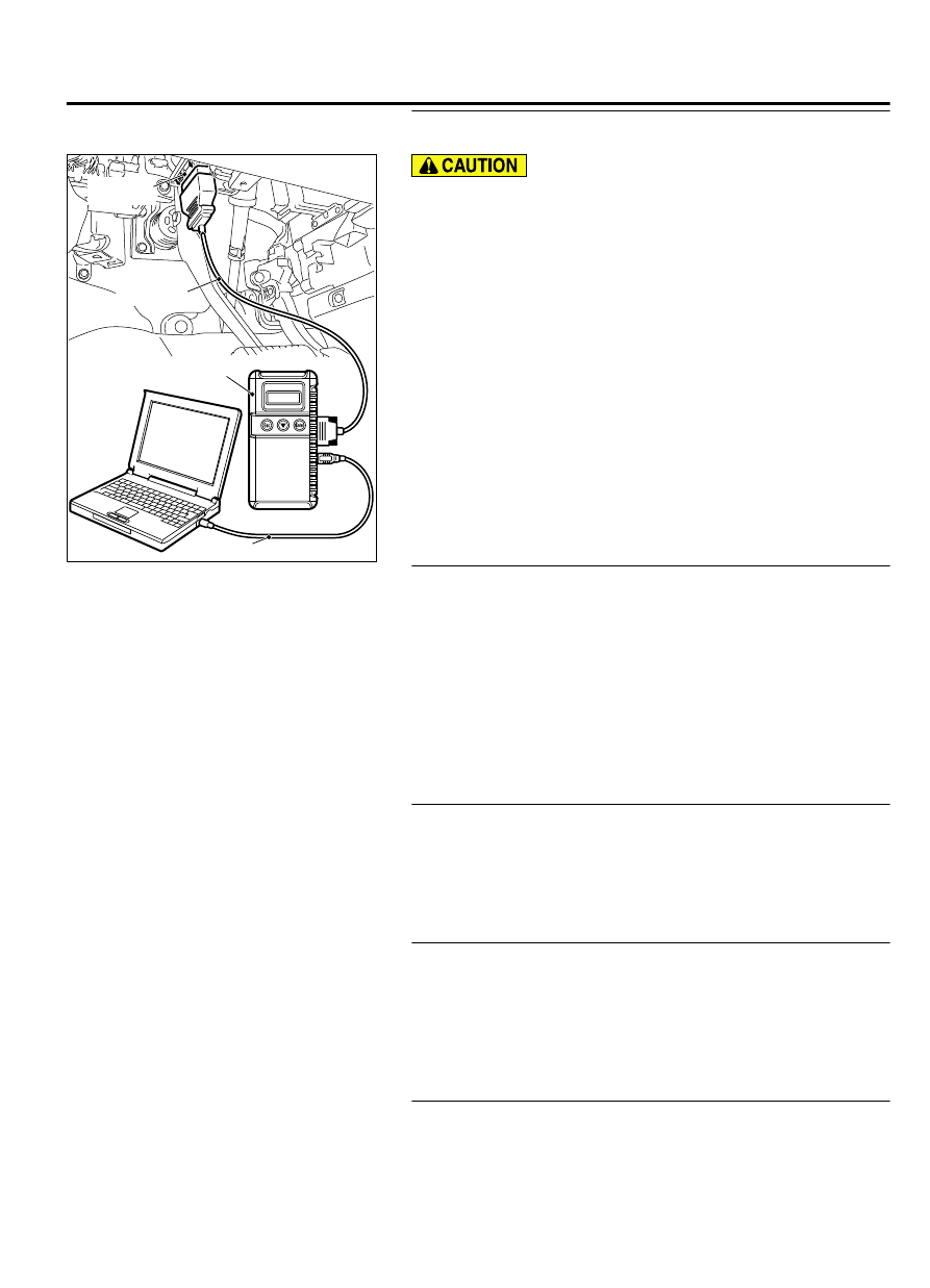
STEP 1. Using scan tool MB991958, diagnose the CAN bus
line.

ZC501967

AC404789

ZC5019680000

MB991824

MB991827

MB991910

Data link

connector

To prevent damage to scan tool MB991958, always turn the
ignition  switch  to  the  "LOCK"  (OFF)  position  before
connecting or disconnecting scan tool MB991958.

(1)

Connect scan tool MB991958. Refer to "How to connect the
Scan Tool (M.U.T.-III) P.42B-10."

(2)

Turn the ignition switch to the "ON" position.

(3)

Diagnose the CAN bus line.

(4)

Turn the ignition switch to the "LOCK" (OFF) position.

Q:Is the CAN bus line found to be normal?

YES:

 Go to Step 2.

NO:

 Repair the CAN bus line. (Refer to GROUP 54D,

Diagnosis P.54D-17).

STEP 2. Using scan tool MB991958, read the other system
diagnostic trouble code.
Check  if  DTC  is  set  to  the  ETACS-ECU  or  engine  control
module.

Q:Is the DTC set?

YES (DTC is set to ETACS-ECU.):

 Troubleshoot the ETACS.

(Refer to GROUP 54Ad, Diagnosis P.54Ad-8.)

YES (DTC is set to the engine control module.):

Troubleshoot the MFI system. (Refer to GROUP 13Ab,
Diagnosis P.13Ab-44.)

NO:

 Go to Step 3.

STEP 3. Check part number of ETACS-ECU.
Check the part number of ETACS-ECU.

OK: 8637A213

Q:Is the check result normal?

YES:

 Go to Step 4.

NO:

 Replace ETACS-ECU.

STEP 4. Check part number of KOS-ECU.
Check the part number of WCM.

OK: 8637A305

Q:Is the check result normal?

YES:

 Go to Step 5.

NO:

 Replace KOS-ECU and register the ID codes. (Refer

to P.42B-12.)

STEP 5. Recheck for diagnostic trouble code.
Check again if the DTC is set to the KOS-ECU.

(1)

Erase the DTC.

KEYLESS OPERATION SYSTEM (KOS)

42B-107

DIAGNOSIS

(2)

Turn the ignition switch from "LOCK" (OFF) position to "ON"
position.

(3)

Check if DTC is set.

(4)

Turn the ignition switch to the "LOCK" (OFF) position.

Q:Is the DTC set?

YES:

 Replace KOS-ECU and register the ID codes. (Refer

to P.42B-12.)

NO:

 The trouble can be an intermittent malfunction (Refer

to GROUP 00 - How to use Troubleshooting/inspection
Service Points - How to Cope with Intermittent
Malfunction P.00-3).

TROUBLE SYMPTOM CHART

M14209100045USA0000010000

Trouble symptom

Inspection
procedure
number

Reference
page

Cannot communicate with KOS-ECU using the scan tool.

1

 P.

42B-109

Abnormality in KOS-ECU power supply and ground circuits

2

 P.

42B-110

Keyless operation warning display does not disappear.

3

 P.

42B-112

IG knob will not turn (keyless operation is not recognized).

4

 P.

42B-114

The engine will not start with KOS (IG knob operates normally).

5

 P.

42B-120

No Door will be Locked or Unlocked by Operating A Lock Switch On Any Door, or
by touching The Unlock Sensor.

6

 P.

42B-121

Driver's Door Lock Switch does not Work.

7

 P.

42B-125

Driver's Door Unlock Sensor does not Work.

8

 P.

42B-128

Front Passenger's Door Lock Switch does not Work.

9

 P.

42B-130

Front Passenger's Door Unlock Sensor does not Work.

10

 P.

42B-133

Lock Switch (Liftgate) does not Work.

11

 P.

42B-136

Liftgate Lock Release Handle does not Work.

12

 P.

42B-140

Keyless Entry System does not Work.

13

 P.

42B-144

KOS Timer Lock Function does not Work.

14

 P.

42B-150

42B-108

KEYLESS OPERATION SYSTEM (KOS)

DIAGNOSIS

Trouble symptom

Inspection
procedure
number

Reference
page

The  Dome  Light  and  The  Turn-signal  Lights  do  not  Operate  through  The
Answerback Function.

15

 P.

42B-151

Outer Tone alarm does not Sound.

16

 P.

42B-153

SYMPTOM PROCEDURES

Inspection Procedure 1: Cannot communicate with KOS-ECU using the scan tool.

M14209100077USA0000010000

ZC6008750000

Connector: C-125

C-125 (B)

ZC6008780000

Connector: C-301

TROUBLESHOOTING HINTS

Damaged wiring harness and connectors

Malfunction of KOS-ECU

DIAGNOSIS

Required Special Tools:

MB991958: Scan Tool (M.U.T.-III Sub Assembly)

MB991824: Vehicles Communication Interface (V.C.I.)

MB991827: M.U.T.-III USB Cable

MB991910:  M.U.T.-III  Main  Harness  A  (Vehicles  with
CAN communication system)

STEP 1. V.C.I. status check
Check that the V.C.I. indicator light is illuminated in green.

Q:Is it illuminated in green?

YES:

 Diagnose the CAN bus line, and repair if necessary.

(Refer to GROUP 54D, Diagnosis P.54D-17.)

KEYLESS OPERATION SYSTEM (KOS)

42B-109

DIAGNOSIS

NO:

 Go to Step 2.

STEP 2. Check ETACS-ECU connector C-301 and data link
connector C-125 for loose, corroded or damaged terminals,
or terminals pushed back in the connector.

Q:Is  the  ETACS-ECU  connector  C-301  and  data  link

connector C-125 in good condition?

YES:

 Go to Step 3.

NO:

 Repair the defective connector.

STEP 3. Check the wiring harness between the ETACS-ECU
connector C-301 (terminal No. 4, 5) and the data link
connector C-125 (terminal No. 14, 6).

Check the power supply line for open circuit.

Q:Is  the  wiring  harness  between  ETACS-ECU  connector

C-301 (terminal No. 4, 5) and the data link connector C-125

(terminal No. 14, 6) in good condition?

YES:

 Go to Step 4.

NO:

 The wiring harness may be damaged or the connector

(s) may have loose, corroded or damaged terminals, or
terminals pushed back in the connector. Repair the wiring
harness as necessary.

STEP 4. Check the wiring harness between the data link
connector C-125 (terminal No. 4, 5) and the ground.

Check the ground wires for open circuit.

Q:Is the wiring harness between data link connector C-125

(terminal No. 4, 5) and the ground in good condition?

YES:

 Check the scan tool (M.U.T.-III). (Refer to M.U.T.-

III User's Manual).

NO:

 Repair the wiring harness.

Inspection Procedure 2: Abnormality in KOS-ECU power supply and ground circuits

M14209100078USA0000010000

Before replacing the ECU, ensure that the power
supply  circuit,  the  ground  circuit  and  the
communication circuit are normal.

42B-110

KEYLESS OPERATION SYSTEM (KOS)

DIAGNOSIS


Content   ..  789  790  791  792   ..