Mitsubishi Outlander XL. Manual - part 727


  Index      Mitsubishi     Mitsubishi Outlander XL - service repair manual 2007 year


Search            


Content   ..  725  726  727  728   ..


Mitsubishi Outlander XL. Manual - part 727


ZC600878

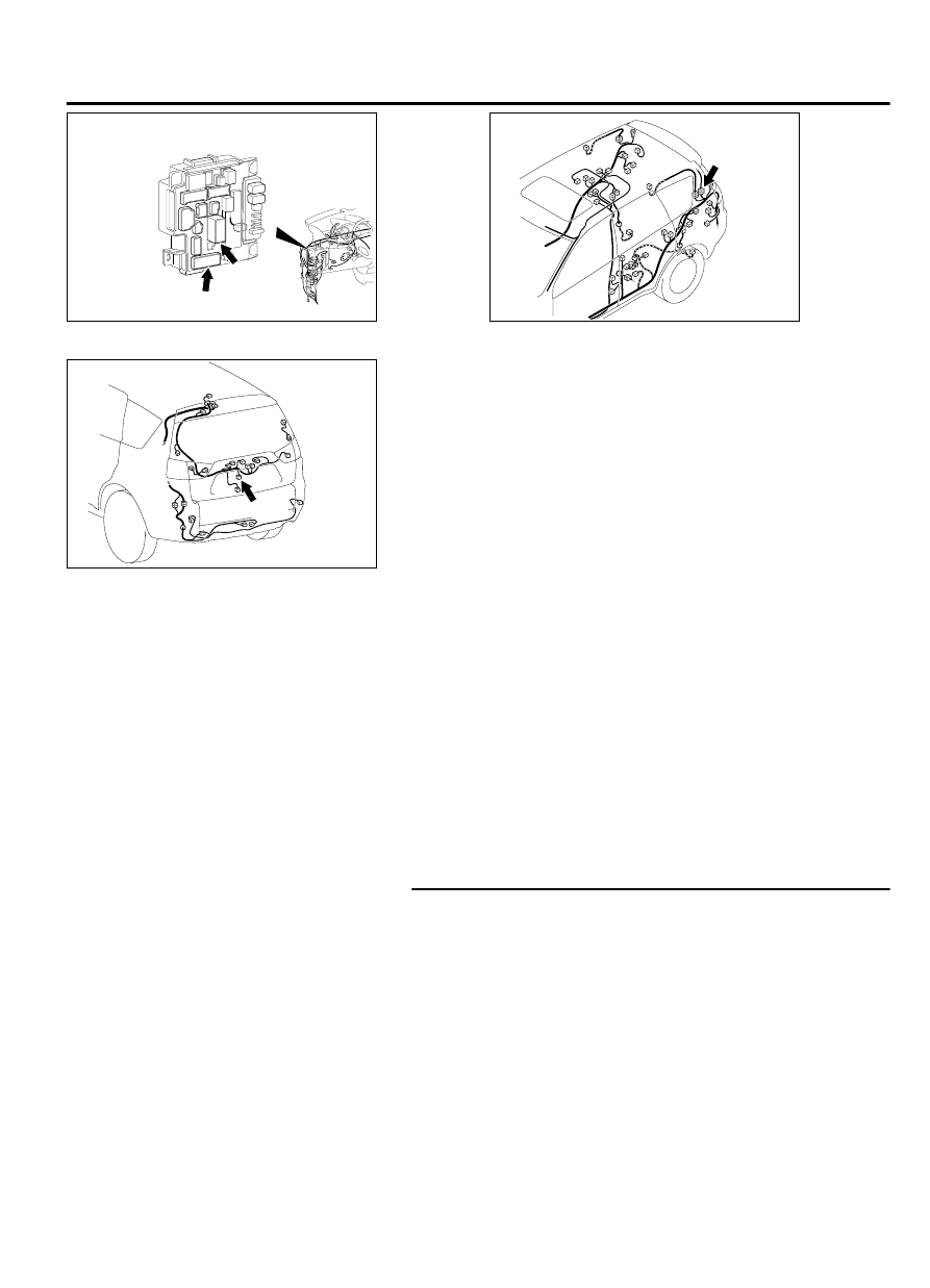
Connectors: C-309, C-311

C-309 (B)

C-311

0012

ZC600880

Connector: D-12

0006


ZC600882

Connector: F-11

0000

F-11 (B)

CIRCUIT OPERATION
The  ETACS-ECU  operates  this  function  in
accordance with the input signals below.

Vehicle speed signal (A/T-ECU)

Liftgate lock release handle

Liftgate lock actuator

TECHNICAL DESCRIPTION (COMMENT)
If this function does not work normally, a malfunction
of  the  input  signal  circuit(s)  mentioned  above  or
ETACS-ECU is suspected.

TROUBLESHOOTING HINTS

Vehicle speed signal (A/T-ECU) error

Malfunction of the liftgate lock release handle

Malfunction of the liftgate lock actuator

Malfunction of ETACS-ECU

Damaged wiring harness and connectors

DIAGNOSTIC PROCEDURE

Required Special Tools:

MB991223: Harness Set

MB992006: Extra Fine Probe

MB991958: Scan Tool (M.U.T.-III Sub Assembly)

MB991824: Vehicles Communication Interface (V.C.I.)

MB991827: M.U.T.-III USB Cable

MB991910: M.U.T.-III Main Harness A

STEP 1. Checking central door unlocking operation
Check that the central door locking system works normally.

Q:Is the check result normal?

YES:

 Go to Step 2.

NO:

 Refer to P.42Ab-11.

DOOR

42Ab-27

CENTRAL DOOR LOCKING SYSTEM DIAGNOSIS

STEP 2. Using scan tool MB991958, read CAN bus the
diagnostic trouble code.

ZC501967

AC404789

ZC5019680000

MB991824

MB991827

MB991910

Data link

connector

To prevent damage to scan tool MB991958, always turn the
ignition  switch  to  the  "LOCK"  (OFF)  position  before
connecting or disconnecting scan tool MB991958.

(1)

Connect scan tool MB991958. Refer to GROUP 54Ad, "How
to connect scan tool (M.U.T.-III) P.54Af-4."

(2)

Turn the ignition switch to the "ON" position.

(3)

Check whether the CAN bus lines related DTC is set.

(4)

Turn the ignition switch to the "LOCK" (OFF) position.

Q:Is the DTC set?

YES:

 Repair the CAN bus line (Refer to GROUP 54D, CAN bus

diagnostics table P.54D-17).

NO:

 Go to Step 3.

STEP 3. Using scan tool MB991958, read the diagnostic
trouble code.

ZC501967

AC404789

ZC5019680000

MB991824

MB991827

MB991910

Data link

connector

To prevent damage to scan tool MB991958, always turn the
ignition  switch  to  the  "LOCK"  (OFF)  position  before
connecting or disconnecting scan tool MB991958.

(1)

Connect scan tool MB991958. Refer to GROUP 54Ad, "How
to connect scan tool (M.U.T.-III) P.54Af-4."

(2)

Turn the ignition switch to the "ON" position.

(3)

Check that the A/T-ECU sets a diagnostic trouble code.

(4)

Turn the ignition switch to the "LOCK" (OFF) position.

Q:Is the DTC set?

YES:

 Diagnose A/T-ECU (Refer to GROUP 23, Diagnostic

Trouble Code Chart P.23A-22).

NO:

 Go to Step 4.

STEP 4. Using scan tool MB991958, check data list.
Check the input signals from the liftgate lock release handle.

42Ab-28

DOOR

CENTRAL DOOR LOCKING SYSTEM DIAGNOSIS

ZC501967

AC404789

ZC5019680000

MB991824

MB991827

MB991910

Data link

connector

To prevent damage to scan tool MB991958, always turn the
ignition  switch  to  the  "LOCK"  (OFF)  position  before
connecting or disconnecting scan tool MB991958.

(1)

Connect scan tool MB991958. Refer to "How to connect the
Scan Tool (M.U.T.-III) P.54Ad-5."

(2)

Turn the ignition switch to the "ON" position.

(3)

Check the data list of the ETACS.

Liftgate lock release handle: from OFF to ON

Item No.

Item name

Normal
condition

Item 230

Trunk / gate opener from  OFF  to

ON

(4)

Turn the ignition switch to the "LOCK" (OFF) position.

OK: Normal condition is displayed.

Q:Is the check result normal?

YES:

 Go to Step 5.

NO:

 Refer to P.42Ab-11.

STEP 5. Check ETACS-ECU connector C-311 for loose,
corroded or damaged terminals, or terminals pushed back
in the connector.

Q:Is ETACS-ECU connector C-311 in good condition?

YES:

 Go to Step 6.

NO:

 Repair or replace the damaged component(s). Refer to

GROUP 00E, Harness Connector Inspection P.00E-2. Verify
that the liftgate can be locked and unlocked normally.

STEP 6. Check the liftgate lock actuator.

ZC6001190000

Lock

Lever

Unlock

Remove the liftgate lock actuator. The illustration shows when
the liftgate lock actuator is viewed from inside the liftgate. Refer
to GROUP 42Ac, Liftgate Handle and Latch P.42Ac-10.

Lever
position

Battery
connection

Lever
operation

At

 the

"LOCK"
position

Connect  terminal
No.  2  to  the
negative  battery
terminal.

Connect  terminal
No.  1  to  the
positive  battery
terminal.

The lever moves
from the "LOCK"
position  to  the
"UNLOCK"
position.

Q:Is the liftgate lock actuator normal?

YES:

 Go to Step 7.

NO:

 Replace the liftgate lock actuator. Verify that the

liftgate can be locked and unlocked normally.

DOOR

42Ab-29

CENTRAL DOOR LOCKING SYSTEM DIAGNOSIS

STEP 7. Check the ground circuit to the liftgate lock
actuator. Measure the resistance at liftgate lock actuator
connector F-11.

(1)

Disconnect  liftgate  lock  actuator  connector  F-11  and
measure  the  resistance  on  the  wiring  harness  side  of  the
connector.

ZC5007880003

Connector F-11 
(harness side)

(2)

Measure  the  resistance  value  between  terminal  2  and
ground.

The resistance should be 2 ohms or less.

Q:Is the measured resistance 2 ohms or less?

YES:

 Go to Step 9.

NO:

 Go to Step 8.

STEP 8. Check the wiring harness between liftgate lock
actuator connector F-11 (terminal 2) and ground.

Q:Is  the  wiring  harness  between  liftgate  lock  actuator

connector  F-11  (terminal  2)  and  ground  in  good

condition?

YES:

 No action is necessary and testing is complete.

NO:

 The wiring harness may be damaged or the connector

(s) may have loose, corroded or damaged terminals, or
terminals pushed back in the connector. Repair the wiring
harness as necessary. Verify that the liftgate can be
locked and unlocked normally.

STEP 9. Check the wiring harness between ETACS-ECU
connector C-311 (terminal 1) and liftgate lock actuator
connector F-11 (terminal 1).

NOTE: 

Also check intermediate connector D-12 for loose,

corroded, or damaged terminals, or terminals pushed back in
the connector. If intermediate connector D-12 is damaged,
repair or replace the damaged component(s) as described in
GROUP 00E, Harness Connector Inspection P.00E-2.

Q:Is  the  wiring  harness  between  ETACS-ECU  connector

C-311  (terminal  1)  and  liftgate  lock  actuator  connector

F-11 (terminal 1) in good condition?

YES:

 Go to Step 10.

NO:

 The wiring harness may be damaged or the connector

(s) may have loose, corroded or damaged terminals, or
terminals pushed back in the connector. Repair the wiring
harness as necessary. Verify that the liftgate can be
locked and unlocked normally.

STEP 10. Retest the system.
Check that the liftgate can be locked and unlocked normally.

Q:Is the check result normal?

YES:

 No action is necessary and testing is complete.

42Ab-30

DOOR

CENTRAL DOOR LOCKING SYSTEM DIAGNOSIS


Content   ..  725  726  727  728   ..