Mitsubishi Outlander XL. Manual - part 605
ZC6010160000
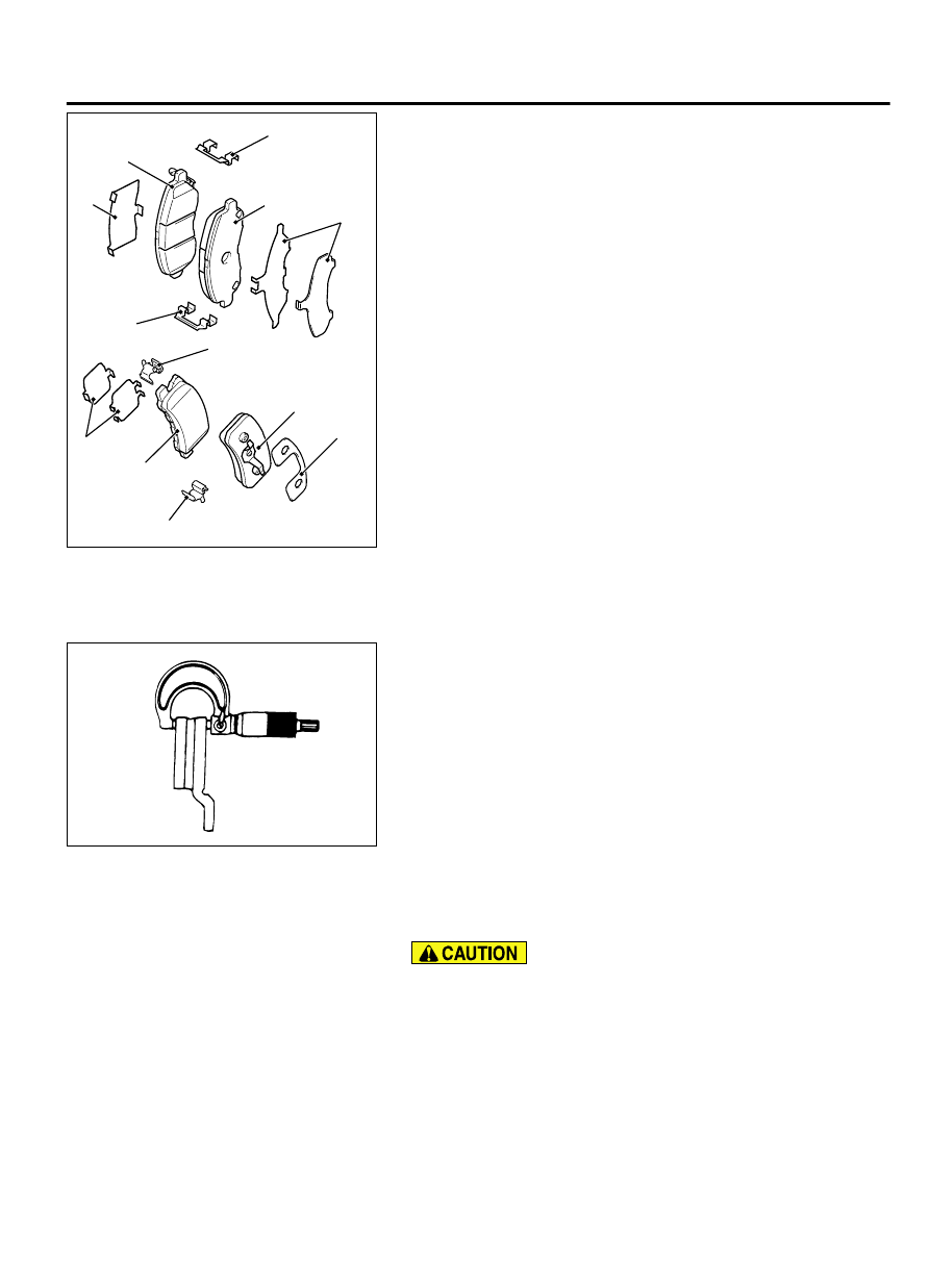
<Front>
<Rear>
2
4
3
5
5
1
4
1
1
1
5
5
4.
Remove the following parts from the caliper assembly.
(1)
Shim
(2)
Pad assembly front
(3)
Pad & clip assembly rear
(4)
Pad assembly RH, pad & wear indicator assembly LH
(5)
Clip
5.
In order to measure the brake drag force after pad installation,
measure the hub sliding torque with no pad attached.(Refer
to P.35A-28.)
6.
Install the pad and caliper assembly, and check the brake drag
force.(Refer to P.35A-28.)
BRAKE DISC THICKNESS CHECK
M13501000024USA0000010000
1.
Remove any dirt and rust on the brake disc surface.
ZC601020 0000
2.
Measure thickness of the brake disc at the sliding area with
the brake pad at four or more points.
Standard value:
Front 26.0 mm (1.02 inch)
Rear 10.0 mm (0.39 inch)
Minimum limit:
Front 24.4 mm (0.96 inch)
Rear 8.4 mm (0.33 inch)
3.
When any one of the thicknesses is lower than the limit value,
replace both brake discs and pads (right and left) as a set.
BRAKE DISC RUNOUT INSPECTION AND
CORRECTION
M13501000094USA0000010000
When working on the brake disc such as for replacement,
make sure that the wheel speed detection magnetic encoder
should not collect foreign materials.
1.
Remove the caliper assembly and hold it with a wire.
2.
Temporarily fix the brake disc with the hub nut.
BASIC BRAKE SYSTEM
35A-21
ON-VEHICLE SERVICE