Mitsubishi Outlander XL. Manual - part 604


  Index      Mitsubishi     Mitsubishi Outlander XL - service repair manual 2007 year


Search            


Content   ..  602  603  604  605   ..


Mitsubishi Outlander XL. Manual - part 604


AC000871

ZC5012370000

When engine
is stopped

When engine
is started

AC000872

ZC5012380000

Good

No good

When one or more of the above check results are "No Good,"
then  the  check  valve,  vacuum  hose,  or  brake  booster  is
suspected faulty.


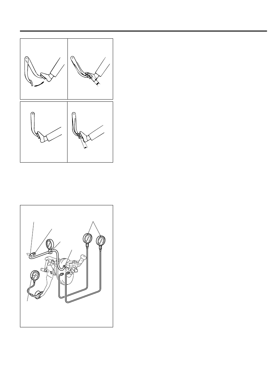
INSPECTION USING SIMPLIFIED TESTER

1.

Before  starting  this  inspection,  remove  the  brake  booster
check valve from the vehicle and check its operation (Refer
to P.35A-14).

ZC6018380000

Pressure gauge

Vacuum 
gauge

Vacuum hose

Check valve

MB992146

Pedal depression
gauge

2.

After checking, install the check valve to the vacuum hose and
connect  it  to  the  vacuum  gauge.  Install  the  booster  test
adapter (Special tool: MB992146) to the brake booster and
connect it to the vacuum gauge. Connect the pressure gauge
and pedal depression gauge as shown in the figure. Bleed the
pressure gauge and then perform the following tests:

(1)

Airtightness test with no load
Start  the  engine,  and  stop  it  when  the  vacuum  gauge
indicator  has  reached  approximately  -67  kPa  (-9.7  psi).
The  result  is  judged  as  "Good"  when  the  drop  of  the
vacuum approximately 15 seconds after the engine was
stopped is within -3.3 kPa (-0.5 psi).

(2)

Airtightness test with load
Start the engine and depress the brake pedal with 200 N.
Stop the engine when the vacuum gauge indicator reached
approximately -67 kPa (-9.7 psi). The result is judged as
"Good"  when  the  drop  of  the  vacuum  approximately  15
seconds after the engine was stopped is within -3.3 kPa
(-0.5 psi).
When one or more of the above check results are judged
as  "No  Good,"  the  vacuum  hose  or  brake  booster  is
suspected faulty.

(3)

Brake booster characteristics test

BASIC BRAKE SYSTEM

35A-17

ON-VEHICLE SERVICE

Perform this test after the above (1) and (2) were performed.

a.

Non-servo effect test
With  the  engine  stopped,  make  sure  that  the  vacuum
gauge reading is 0 kPa (0 psi). Depress the brake pedal
with  100  N  and  300  N,  and  measure  the  fluid  pressure
generated.

Standard value:

Item

Pedal depression force
100 N

300 N

Generated  fluid
pressure

 kPa

(psi)

200  (29)  or
more

1,800 (261) or
more

b.

Servo effect test
Start the engine. Depress the brake pedal with 100 N and
300  N  when  the  vacuum  gauge  indicator  reached
approximately  -67  kPa  (-9.7  psi),  and  measure  the  fluid
pressure generated.

Standard value:

Item

Pedal depression force
100 N

300 N

Generated  fluid
pressure

 kPa

(psi)

6,050  -  7,950
(877 - 1,153)

10,720 (1,554)
or more

CHECK VALVE OPERATION CHECK

M13501000090USA0000010000

1.

Remove the check valve.(Refer to P.35A-18.)

ZC601004

Valve

Spring

Intake  
manifold 
side

Booster side

(1)

(2)

0000

Replace the check valve when it is faulty.

2.

Using a vacuum pump, check operation of the check valve.

Vacuum

 pump

connection

Normal condition

When  connected  to  the
booster side (1)

Vacuum  is  generated
and maintained.

When  connected  to  the
engine side (2)

No vacuum is generated.

BLEEDING

M13501000014USA0000010000

Be sure to use the specified brand and type of brake fluid.
Avoid mixing with other type of brake fluid.

Brake fluid:
Mitsubishi Genuine Diamond Queen Brake Fluid Super
4

35A-18

BASIC BRAKE SYSTEM

ON-VEHICLE SERVICE

BLEEDING OF MASTER CYLINDER
When removed the master cylinder assembly, bleed the master
cylinder in the following procedure to make bleeding of the brake
pipeline easier. (When no brake fluid is in the master cylinder)

1.

Fill the brake fluid reservoir with the brake fluid.

2.

Depress and hold the brake pedal.

ZC6018390000

Master cylinder

Outlet

3.

Another operator closes the master cylinder outlets with his
fingers.

4.

In this condition, release the brake pedal.

5.

Repeat Steps 2 to 4 for 3 or 4 times to fill the master cylinder
with the brake fluid.


BLEEDING OF BRAKE PIPELINE

ZC6010090000

1

2

3

4

Front of
vehicle

1.

Perform the bleeding in the order shown in the figure.

BRAKE FLUID LEVEL SWITCH CHECK

M13501000091USA0000010000

ZC6010100000

The  brake  fluid  level  switch  is  normal  when  the  following
conditions are met: When the brake fluid level is above "MIN,"
continuity  is  detected;  and  when  the  level  is  below  "MIN,"  no
continuity is detected.

BASIC BRAKE SYSTEM

35A-19

ON-VEHICLE SERVICE

DISC BRAKE PAD CHECK AND REPLACEMENT

M13501000023USA0000010000

ZC6010120000

<Front>

ZC6010130000

<Rear>

1.

Visually check the thickness of brake pad from the inspection
hole of the caliper body.

Standard value: 10.0 mm (0.39 inch)
Minimum limit: 2.0 mm (0.08 inch)

2.

When the thickness is lower than the limit value, replace both
brake pads (right and left) as a set.

ZC6010140000

<Front>

Guide pin

ZC6010150000

<Rear>

Lock pin

3.

Remove  the  parts  indicated  in  the  figure,  swivel  the  caliper
assembly upward and retain it with a wire or similar tool.

35A-20

BASIC BRAKE SYSTEM

ON-VEHICLE SERVICE


Content   ..  602  603  604  605   ..