Mitsubishi Outlander XL. Manual - part 603


  Index      Mitsubishi     Mitsubishi Outlander XL - service repair manual 2007 year


Search            


Content   ..  601  602  603  604   ..


Mitsubishi Outlander XL. Manual - part 603


STEP 2. Check for looseness of the wheel nuts.

Q:Are the wheel nuts loose?

YES:

 Tighten to 98 ± 10 N·m (73 ± 7 ft-lb). Then go to

Step 5.

NO:

 Go to Step 3.

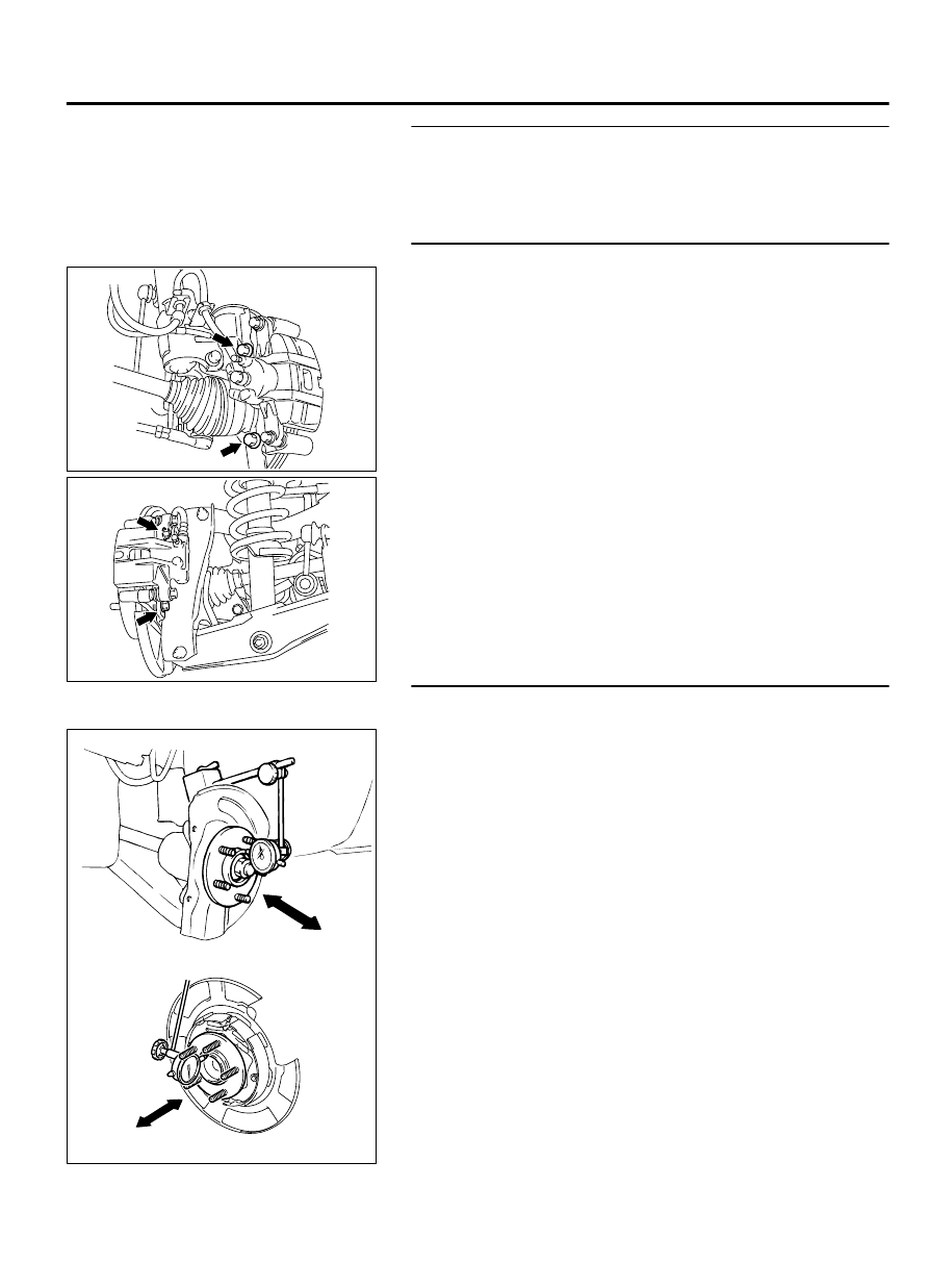
STEP 3. Check for looseness of the caliper installation bolt.

ZC6010140001

<Front>

ZC6010150001

<Rear>

Q:Is the caliper installation bolt loose?

YES:

 Tighten to 100 ± 10 N·m (74 ± 7 ft-lb) for the

front caliper. Tighten to 60 ± 5 N·m (45 ± 3 ft-lb) for
the rear caliper. Then go to Step 5.

NO:

 Go to Step 4.

STEP 4. Check the wheel bearings for end play.

(1)

Remove the brake discs.

ZC6010220000

<Front>

<Rear>

(2)

Place a dial gauge as shown, and measure the end play while
moving the hub in the axial direction.

Limit: 0.05 mm (0.002 inch)

Q:Does the measured end play exceed the limit?

YES:

 Replace the faulty hub assembly. Then go to Step 5.

NO:

 Go to Step 5.

BASIC BRAKE SYSTEM

35A-13

BASIC BRAKE SYSTEM DIAGNOSIS

STEP 5. Recheck symptom.

Q:Is the symptom eliminated?

YES:

 The procedure is complete.

NO:

 Start over at step 1. If a new symptom surfaces,

refer to the symptom chart.

SPECIAL TOOL

M13501000006USA0000010000

Tool

Number

Name

Use

MB992146

MB992146

Booster

 test

adapter

Inspection using a simplified tester

MB990964

A

B

MB990964

A: MB990520

Brake tool set
A: Piston expander

Disc brake piston pushing back

ON-VEHICLE SERVICE

BRAKE PEDAL CHECK

M13501000009USA0000010000

BRAKE PEDAL HEIGHT CHECK

1.

Turn up the floor carpet under the brake pedal.

2.

Remove the stoplight switch. (Refer to P.35A-22.)

ZC6010000000

B

A

Floorboard

Floorboard pad

Stop light
switch

3.

Use a needle or similar tool to measure the dimension A in the
figure (distance from the dash panel pad surface to the dash
panel).

4.

Measure the dimension B in the figure (distance from the pedal
pad surface to the dash panel pad surface).

5.

Make sure that the total of the dimensions A and B measured
in Steps 2 and 3 (brake pedal height) is within the standard
value.

Standard value (A+B): 221.8 - 227.8 mm (8.7 - 9.0 inch)

35A-14

BASIC BRAKE SYSTEM

SPECIAL TOOL

ZC6010010000

C

Clevis

Stud bolt

6.

When the brake pedal height is not within the standard value,
inspect the brake pedal in the following procedure.

(1)

Remove the brake pedal assembly. (Refer to P.35A-22.)

(2)

Check the removed brake pedal assembly for distortion,
and replace it when deformed. (Refer to P.35A-22.)

(3)

Install the brake pedal assembly. (Refer to P.35A-22.)

NOTE: 

When installing, compress the dash panel pad.

(4)

Measure the brake pedal height again, and make sure that
it is within the standard value (A+B).
When the measured value is not within the standard value,
measure the dimension C in the figure (distance from the
stud bolt end to the clevis hole center), and make sure it is
within the standard value (C).

Standard value (C): 75.8 - 80.2 mm (2.98 - 3.16 inch)

(5)

When the measured value is not within the standard value
(C), replace the brake booster.(Refer to P.35A-22.)

ZC6010020000

0.5 to 1.5 mm

Stop light switch

Pedal stoppe r

Pedal stoppe r

7.

After  checking  the  brake  pedal  height,  install  the  stoplight
switch in the following procedure:

(1)

Screw in the stoplight switch until its thread contacts the
pedal  stopper,  then  turn  the  switch  approximately  one
eighth of a clockwise turn to fix it. While doing this, pull and
hold the brake pedal by hand.

(2)

Check that the clearance between the stoplight switch and
the pedal stopper is as shown in the figure.

Make sure that the stoplight is not illuminated when the
brake pedal is not depressed.

(3)

Connect the stoplight switch connector.

8.

Check  the  key  interlock  mechanism  and  the  shift  lock
mechanism. (Refer to GROUP 23 - On-vehicle Service, Key
Interlock  Mechanism  Check  P.23A-162,  Shift  Lock
Mechanism Check P.23A-163.)

9.

Recover the floor carpet under the brake pedal.


BASIC BRAKE SYSTEM

35A-15

ON-VEHICLE SERVICE

BRAKE PEDAL PLAY CHECK AND ADJUSTMENT

ZC6010000001

D

1.

With the engine stopped, depress the brake pedal 2 or 3 times
to relieve the vacuum in the brake booster. Then, press the
brake pedal with your finger and check if the pedal stroke until
the pedal becomes heavy (play) is within the standard value.

Standard value (D): 3 - 8 mm (0.12 - 0.31 inch)

2.

When the brake pedal play is not within the standard value,
check the brake pedal-to-clevis pin looseness, clevis pin-to-
booster  operating  rod  looseness,  brake  pedal  height,  and
stoplight switch position, and adjust or replace as necessary.

BRAKE PEDAL-TO-FLOOR PANEL CLEARANCE CHECK
AND ADJUSTMENT

1.

Turn up the floor carpet under the brake pedal.

ZC6010000002

E

2.

Start  the  engine  and  depress  the  brake  pedal  with
approximately 500 N (112 pounds), and measure clearance
between the brake pedal and the floor panel.

Standard value (E): 80 mm (3.15 inch) or more

3.

When the clearance is not within the standard value, check for
the air in the brake line and thickness of the disc brake pad,
and correct or replace as necessary.

4.

Recover the floor carpet under the brake pedal.

BRAKE BOOSTER OPERATION CHECK

M13501000010USA0000010000

INSPECTION WITHOUT USING TESTER

AC000870

ZC501236 0000

Good

No good

Once

Second

Third

1.

Carry out the simplified brake booster operation check in the
following procedure:

(1)

Run the engine for 1 to 2 minutes, and then stop. Depress
the brake pedal with normal depression force. The result
is judged as "Good" when the pedal stroke is great at the
first  depression,  and  becomes  smaller  as  you  repeat
depressing the pedal. If the pedal stroke does not change,
the result is judged as "No Good."

(2)

With the engine stopped, depress the brake pedal several
times.  Keep  the  brake  pedal  depressed  and  start  the
engine. At this time, when the pedal moves down slightly,
the result is judged as "Good." The result is judged as "No
Good" if the pedal does not moves down.

(3)

With the engine running, depress the brake pedal. Stop the
engine  in  this  condition.  The  result  is  judged  as  "Good"
when the pedal height does not change for approximately
30 seconds. The result is judged as "No Good" if the pedal
moves up.

2.

The brake booster is judged as normal when the results of all
the above checks are "Good."

35A-16

BASIC BRAKE SYSTEM

ON-VEHICLE SERVICE


Content   ..  601  602  603  604   ..