Mitsubishi Outlander XL. Manual - part 587
ENGINE MOUNTING
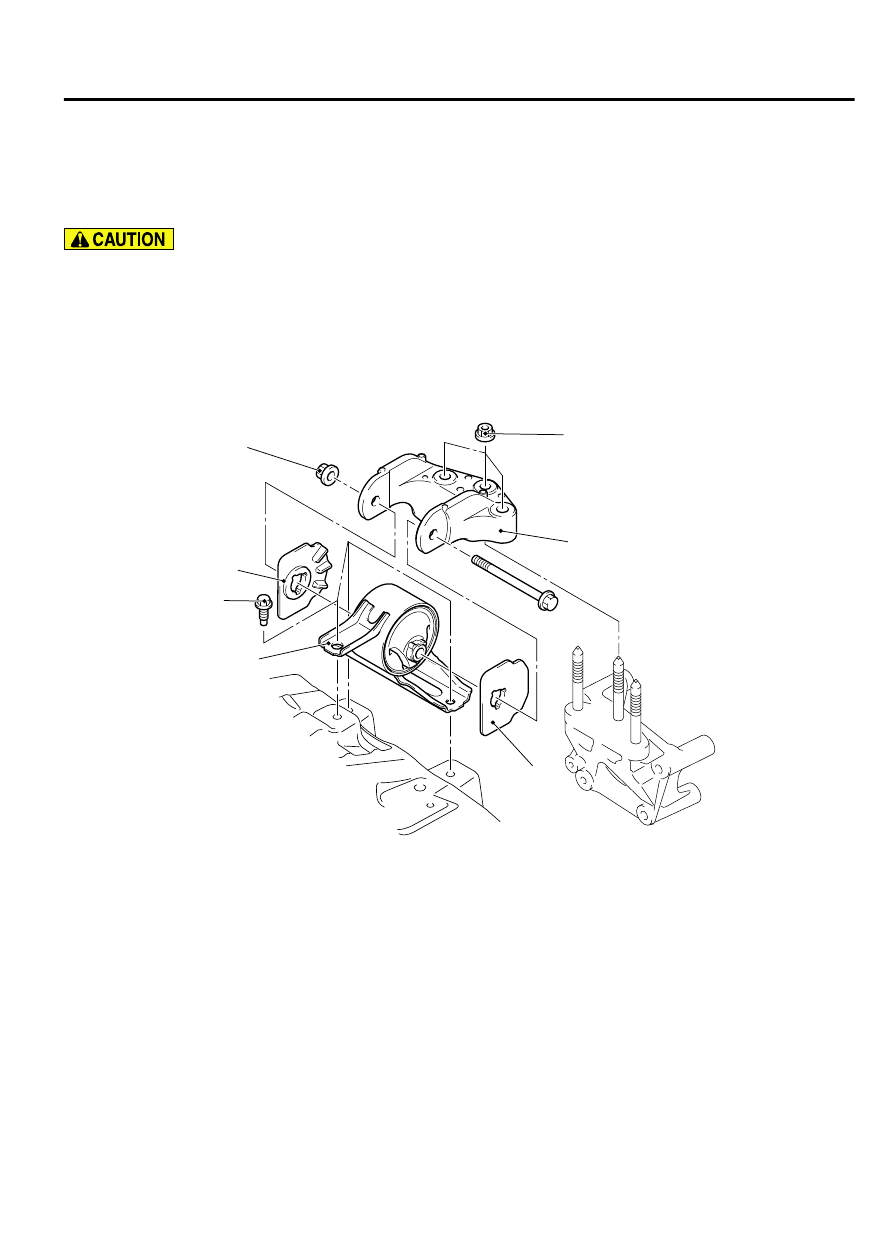
REMOVAL AND INSTALLATION
M13201000011USA0000010000
*: Indicates parts which should be initially
tightened, and then fully tightened after placing
the vehicle horizontally and loading the full weight
of the engine on the vehicle body.
Pre-removal operation
⦆
Radiator Condenser Tank Removal (Refer to GROUP 14,
⦆
Power Steering Oil Pump Assembly Removal (Refer to
GROUP 37, Power Steering Oil Pump Assembly P.37-34).
⦆
Raise the engine and transaxle assembly until its weight is not
applied to the insulator, and support it securely.
Post-installation operation
⦆
Power Steering Oil Pump Assembly Installation (Refer to
GROUP 37, Power Steering Oil Pump Assembly P.37-34).
⦆
Radiator Condenser Tank Installation (Refer to GROUP 14,
AC506146
ZC600538AA00
1
2
2
3
50 ± 5 N·m
37 ± 4 ft-lb
82 ± 8 N·m
60 ± 5 ft-lb
100 ± 5 N·m*
74 ± 4 ft-lb*
Removal steps
1.
Engine mounting bracket
>>A<<
2.
Engine mounting insulator stopper
Removal steps
3.
Engine mounting insulator
POWER PLANT MOUNT
32-3
ENGINE MOUNTING