Mitsubishi Outlander XL. Manual - part 586


  Index      Mitsubishi     Mitsubishi Outlander XL - service repair manual 2007 year


Search            


Content   ..  584  585  586  587   ..


Mitsubishi Outlander XL. Manual - part 586


ON-VEHICLE SERVICE

TIRE INFLATION PRESSURE CHECK

M13101000009USA0000010000

NOTE: 

For information on tire inflation pressure, refer to

the label attached to the center pillar on the driver's
side.

NOTE: 

The TPMS is not a substitute for regular checks of

the tire inflation pressure. Be sure to check the tire
inflation pressure as usual.

TIRE WEAR CHECK

M13101000010USA0000010000

Measure the tread depth of the tires.

Minimum limit: 1.6 mm (0.063 inch)

If  the  remaining  tread  depth  is  less  than  the  minimum  limit,
replace the tire.

NOTE: 

When the tread depth of the tires is reduced to 1.6

mm (0.063 inch) or less, wear indicators will appear.
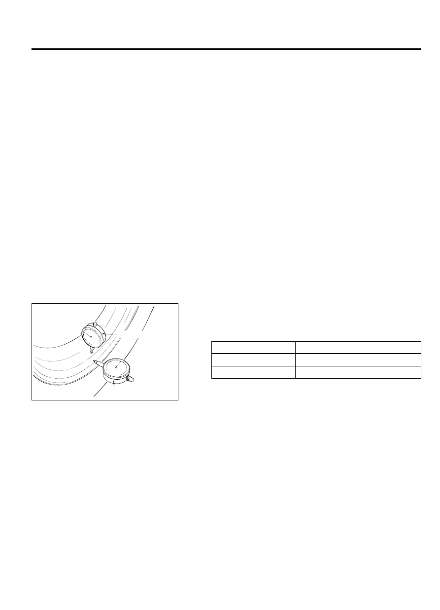
WHEEL RUNOUT CHECK

M13101000011USA0000010000

ZC6008300000

Lateral

Radial

Jack up the vehicle so that the wheels are clear of the floor. While
slowly  turning  the  wheel,  measure  wheel  runout  with  a  dial
indicator.

Limit:

ITEM

ALUMINUM WHEEL

Radial runout

1.0 mm (0.039 inch) or less

Lateral runout

1.0 mm (0.039 inch) or less

If wheel runout exceeds the limit, replace the wheel.

WHEEL AND TIRE

INSTALLATION SERVICE POINT

M13101000013USA0000010000

Tighten the wheel nuts to the specified torque.

Tightening torque: 98 ± 10 N·m (73 ± 7 ft-lb)

WHEEL AND TIRE

31-7

ON-VEHICLE SERVICE

MEMO

31-8

WHEEL AND TIRE

GROUP 32

POWER PLANT MOUNT

CONTENTS

GENERAL INFORMATION.............

32-2

SPECIAL TOOL....................

32-2

ENGINE MOUNTING.................

32-3

REMOVAL AND INSTALLATION........

32-3

TRANSAXLE (TRANSMISSION) MOUNTING
................................

32-4

REMOVAL AND INSTALLATION........

32-4

ENGINE ROLL STOPPER AND CENTERMEMBER
................................

32-6

REMOVAL AND INSTALLATION........

32-6

CROSSMEMBER.....................

32-7

REMOVAL AND INSTALLATION........

32-7

32-1

GENERAL INFORMATION

M13201000001USA0000010000

For the power plant support, the inertial axis four-point
mounting system is utilized, and the system has the
following features.

For  the  engine  and  transaxle  mountings,  the
cylindrical  liquid  seal  mountings  are  used.  This
reduces idling vibration and acceleration noise, and
improves riding comfort.

For the engine mounting bracket, light weight and
high  rigidity  aluminum  is  used  to  reduce
acceleration noise.

For the transaxle mounting bracket, light weight and
high  rigidity  sheet  metal  is  used  to  reduce  gear
noise.

For  the  front  and  rear  roll  stoppers,  insulators
developed for 6A/T are utilized. This reduces idling
vibration and acceleration/deceleration shock.

A flat crossmember improves steering ability.

CONSTRUCTION DIAGRAM

ZC6005360001

Engine mounting
insulator 

Engine mounting 
bracket 

Front roll stopper 

Flat crossmember 

Rear roll stopper 

Transaxle mounting
insulator 

Transaxle mounting  
bracket 

<AWD> 

<FWD> 

SPECIAL TOOL

M13201000006USA0000010000

Tool

Tool  number  and
name

Supersession

Application

YB991897AA00

MB991897

 or

MB992011
Ball joint remover

MB991113-01,
MB990635-01

 or

General service tool

Knuckle and tie rod end ball joint
disconnection

NOTE: 

Steering linkage puller

(MB990635 or MB991113)is also
used to disconnect the knuckle
and tie rod end ball joint.

32-2

POWER PLANT MOUNT

GENERAL INFORMATION


Content   ..  584  585  586  587   ..