Mitsubishi Outlander XL. Manual - part 556
ZC6000010000
12
23
30
5
29
22
21
27
32
25
24
26
28
33
1
9
16
N
N
4
N
N
31
N
19
18
17
11
3
2
N
6
10
9
7
8
10
11
12
14 13
15 1617
18
19
20
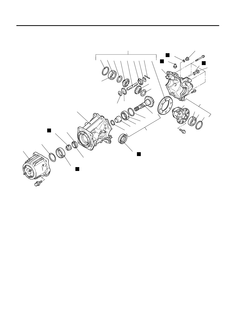
Disassembly steps
<<A>>
·
Inspection before disassembly
1.
Filler plug
2.
Gasket
3.
Drain plug
4.
Gasket
5.
Electronic control coupling
6.
Washer
7.
Differential cover assembly
8.
Vent plug
<<B>>
9.
Differential case assembly
<<B>>
10. Differential side bearing spacer
<<B>>
11. Differential side bearing outer race
<<C>>
12. Differential side bearing inner race
<<D>>
13. Drive gear
Disassembly steps
<<E>>
14. Lock pin
15. Pinion shaft
16. Pinion gear
17. Pinion washer
18. Side gear
19. Side gear spacer
20. Differential case
<<F>>
21. Differential nut
22. Drive pinion assembly
23. Drive pinion front shim (for drive
pinion rotation torque adjustment)
24. Drive pinion spacer
<<G>>
25. Drive pinion rear bearing inner race
26. Drive pinion rear shim (for drive pinion
height adjustment)
REAR AXLE<AWD>
27B-27
DIFFERENTIAL CARRIER ASSEMBLY