Mitsubishi Outlander XL. Manual - part 554
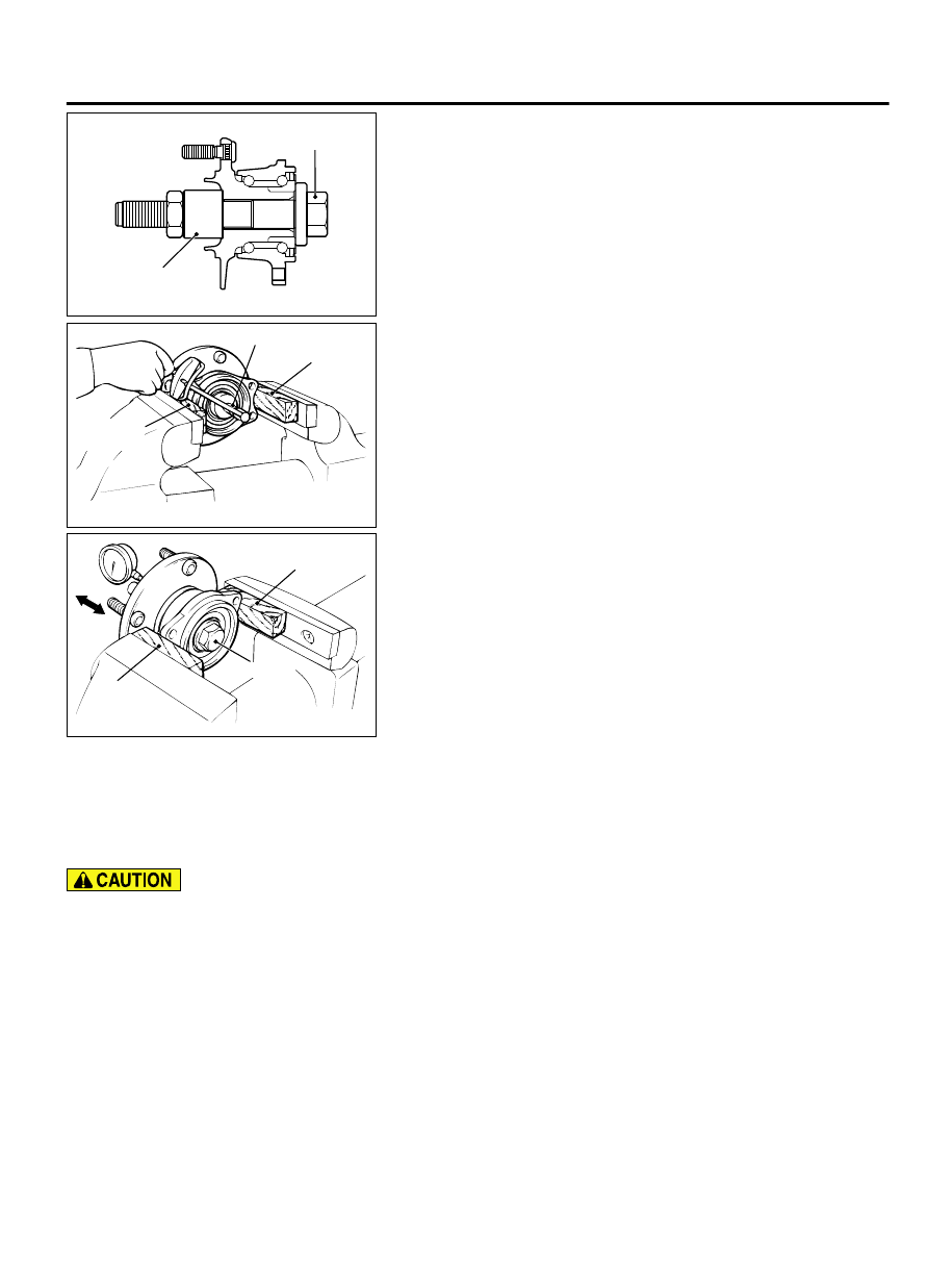
ZC5019990000
MB991000
MB990998
1.
Tighten special tools MB990998 and MB991000 to the
specified torque.
Tightening torque: 160 ± 16 N·m (118 ± 11 ft-lb)
2.
Fix the hub in a vice using a piece of wood or the like.
3.
Rotate the rear hub in order to seat the bearing.
ZC3003310000
MB990326 Wooden
block
Wooden
block
4.
Use special tool MB990326 to measure the hub rotation
starting torque.
Limit value: 1.4 N·m (1.03 ft-lb)
5.
If the hub rotation starting torque at the specified tightening
torque [160 ± 16 N·m (118 ± 11ft-lb)] exceeds the limit value,
replace the hub. If there are rough or gritty feelings in rotation,
replace the hub.
ZC3003320000
MB990998
Wooden
block
Wooden
block
6.
Set a dial gauge, and move the hub in the axial direction to
measure the wheel bearing end play.
Limit: 0.05 mm (0.002 inch)
7.
If the wheel bearing end play at the specified tightening torque
[160 ± 16 N·m (118 ± 11ft-lb)] exceeds the limit value, replace
the hub.
DRIVE SHAFT ASSEMBLY
REMOVAL AND INSTALLATION
M12701000033USA0000010000
When removing and installing the rear wheel
speed sensor, make sure that its pole piece at the
end does not contact with surrounding parts to
avoid damage.
Pre-installation Operation
⦆
Differential Gear Oil Draining
⦆
Disconnect joints between Lower Arm, Trailing Arm, Shock
Absorber, and Stabilizer Link. (Refer to GROUP 34 - Control
Link, Upper Arm, Lower Arm Removal and Installation P.
⦆
Disconnect joint between Upper Arm and Trailing Arm. (Refer
to GROUP 34- Control Link, Upper Arm, Lower Arm Removal
and Installation P.34-10.)
Post-installation Operation
⦆
Connect Upper Arm and Trailing arm. (Refer to GROUP 34 -
Control Link, Upper Arm, Lower Arm Removal and
⦆
Connect Lower Arm, Trailing Arm, Shock Absorber, and
Stabilizer Link. (Refer to GROUP 34 - Control Link, Upper Arm,
Lower Arm Removal and Installation P.34-10.)
⦆
Differential Gear Oil Filling (Refer to P.27B-15.)
⦆
Rear Wheel Alignment Check and Adjustment (Refer to
GROUP 34, On-vehicle Service-Rear Wheel Alignment Check
REAR AXLE<AWD>
27B-19
DRIVE SHAFT ASSEMBLY