Mitsubishi Outlander XL. Manual - part 555


  Index      Mitsubishi     Mitsubishi Outlander XL - service repair manual 2007 year


Search            


Content   ..  553  554  555  556   ..


Mitsubishi Outlander XL. Manual - part 555


LUBRICATION POINTS

ZC3051660000

CAUTIO N

Grease: Repair kit grease
Amount used: 75 ± 10 g (2.6 ± 0.3 oz) 

The drive shaft joint uses special 
grease. Do not mix old and new or 
different types of grease.


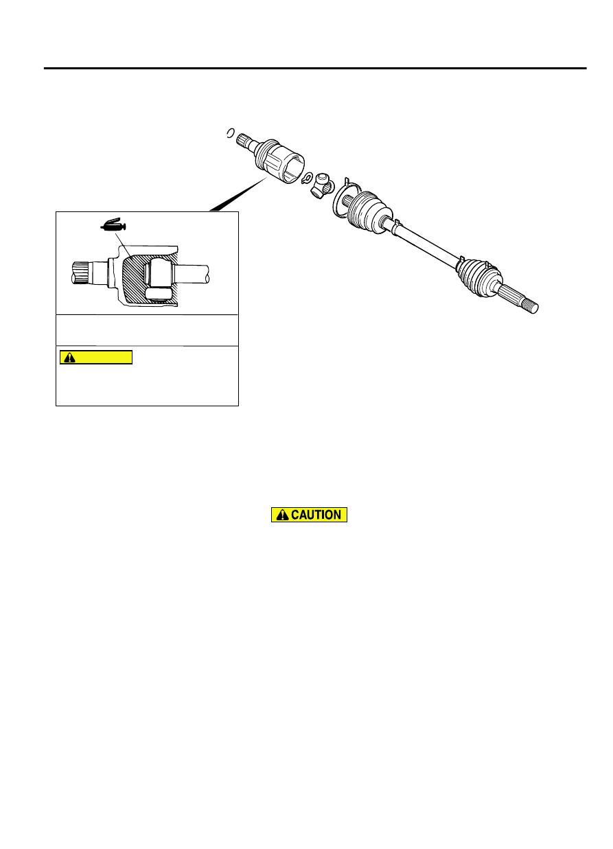
DISASSEMBLY SERVICE POINT

<<A>> ETJ CASE/SPIDER ASSEMBLY REMOVAL

Do not disassemble the spider assembly.

1.

Wipe off the grease inside the ETJ case and on the spider
assembly.

2.

If the grease is contaminated with the foreign material (water,
dust, etc.), be sure to wash the spider assembly.

<<B>> ETJ BOOT REMOVAL

1.

Wipe off the grease on the shaft spline.

2.

If the ETJ boot is reused, protect the shaft spline area with
taping from the damage in removal of the boot.

REAR AXLE<AWD>

27B-23

DRIVE SHAFT ASSEMBLY

ASSEMBLY SERVICE POINT

>>A<< SPIDER ASSEMBLY/ETJ CASE INSTALLATION

Special grease is used for the joint. Do not mix the new and
previous types of grease or different types of grease.

ZC3001250000

Fill the ETJ case with the specified grease, insert the drive shaft,
and then fill the specified grease again.

Specified grease: Repair kit grease
Application amount: 75 ± 10 g (2.6 ± 0.3 oz)

NOTE: 

When using the repair kit grease, fill the half of

the grease into the joint and the other half into the boot
as a guideline, and consume the grease completely.

>>B<< ETJ BOOT BAND (SMALL)/ETJ BOOT BAND
(LARGE) TIGHTENING

ZC3001260000

A

Adjust  the  distance  between  the  boot  bands  to  the  standard
value to adjust the air volume inside the ETJ boot to the specified
value, then be sure to tighten the ETJ boot band (large) and ETJ
boot band (small).

Standard value (A): 75 ± 3 mm (2.95 ± 0.12 inches)

DIFFERENTIAL CARRIER ASSEMBLY

REMOVAL AND INSTALLATION

M12701000904USA0000010000

The  parts  indicated  by  *  are  the  bolts  with
friction coefficient stabilizer. In removal, ensure

there is no damage, clean dust and soiling from
the  bearing  and  thread  surfaces,  and  tighten
them to the specified torque.

Pre-removal Operation

Spare Tire Removal

Exhaust Pipe and Main Muffler Removal (Refer to GROUP 15,

Exhaust Pipe and Muffler P.15-16.)

Differential Gear Oil Draining

Driveshaft Removal (Refer to P.27B-19).

Post-installation Operation

Driveshaft Installation (Refer to P.27B-19).

Differential Gear Oil Filling (Refer to P.27B-15).

Exhaust Pipe and Main Muffler Installation (Refer to GROUP

15, Exhaust Pipe and Muffler P.15-16.)

Spare Tire Installation

27B-24

REAR AXLE<AWD>

DIFFERENTIAL CARRIER ASSEMBLY

ZC5020030000

52 ± 2 N·m
38 ± 2 ft-lb

95 ± 14 N·m
70 ± 10 ft-lb

71 ± 10 N·m
52 ± 7 ft-lb

3

1

2

9

4

7

5

6

8

10

N

32 ± 2 N·m
23 ± 2 ft-lb

7

6

8

10

*

*

110 ± 11 N·m
81 ± 8 ft-lb

*

71 ± 10 N·m
52 ± 7 ft-lb

95 ± 14 N·m
70 ± 10 ft-lb

Removal steps

<<A>>

1.

Propeller shaft connection

2.

Drain plug

3.

Gasket

4.

Cover

5.

Electronic  control  coupling  harness
connection, vacuum hose connection

Removal steps

6.

Weight

7.

Lower stopper

8.

Upper stopper

>>A<<

9.

Differential carrier assembly

10. Differential mount bracket (LH/RH)


REAR AXLE<AWD>

27B-25

DIFFERENTIAL CARRIER ASSEMBLY

REMOVAL SERVICE POINTS

<<A>> PROPELLER SHAFT DISCONNECTION

ZC5018170000

Mating marks 

1.

Put mating marks on the flange yoke and the electronic control
coupling.

2.

Hold the disconnected propeller shaft with a wire so that it will
not hang at a sharp angle.

INSTALLATION SERVICE POINTS

>>A<< DIFFERENTIAL CARRIER ASSEMBLY
INSTALLATION

ZC5020040000

A

Electronic control
coupling

1.

Check that the length of the electronic control coupling stud
bolt (A) is within the standard value range.

Standard value: 22.3 - 25.1 mm (0.88 - 0.99 inch)

2.

If the length exceeds the standard value, replace the stud bolt.

Specified torque: 15 ± 3 N·m (11 ± 2 ft-lb)

NOTE: 

When replacing the stud bolts, always clean the

stud bolt threaded holes.

DISASSEMBLY

M12701000905USA0000010000

27B-26

REAR AXLE<AWD>

DIFFERENTIAL CARRIER ASSEMBLY


Content   ..  553  554  555  556   ..