Mitsubishi Outlander XL. Manual - part 512


  Index      Mitsubishi     Mitsubishi Outlander XL - service repair manual 2007 year


Search            


Content   ..  510  511  512  513   ..


Mitsubishi Outlander XL. Manual - part 512


Inspectio
n
procedur
e

Check conditions

Items to be checked (Normal conditions)

1

Brake

 pedal:

Depress

Ignition  switch  position:
"LOCK" (OFF) or removed

The  selector  lever  cannot  be  moved  out  of  "P"
position.

2

Ignition  switch  position:
"ON"

The selector lever can be moved from "P" position
to other positions smoothly.

3

Transmission range: Other than P

The  ignition  switch  cannot  be  turned  to  the
"LOCK" (OFF) position.

4

Transmission range: P

The  ignition  switch  can  be  turned  to  the
"LOCK" (OFF) position smoothly.
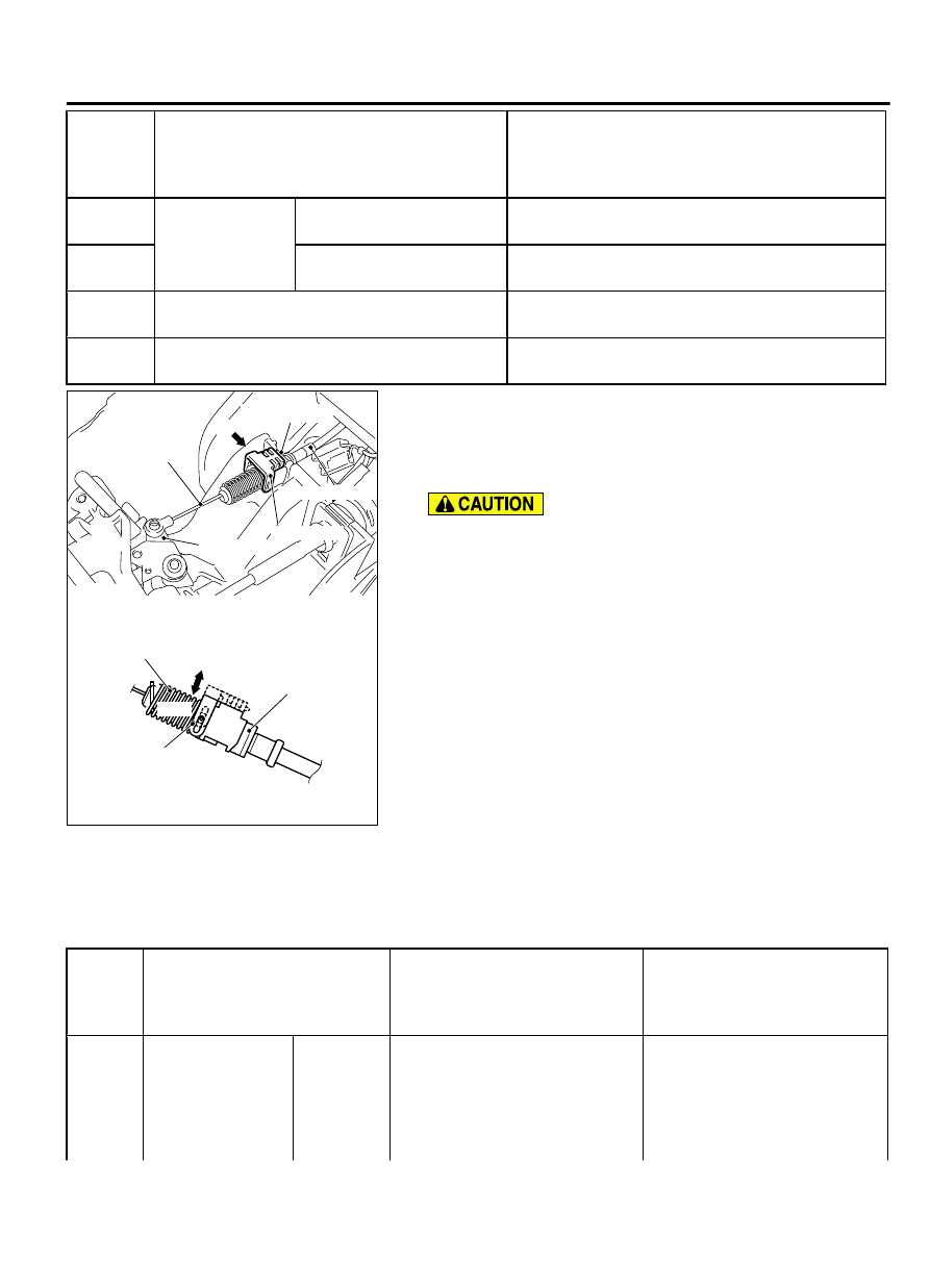
ZC6022240000

Key inter lock cable

A

View A

Spring

Lock

Adjuster case

Adjuster case

Inner cable

Lock guide

Lock guide

Lock cam

Unlock

2.

If the normal conditions are not obtained after performing the
above  operations,  install  the  key  interlock  cable  in  the
following procedures. (Automatic adjustment)

(1)

Disconnect  the  key  interlock  cable  connection  (selector
lever side).(Refer to P.23A-168.)

Leave the ignition switch in the "LOCK" (OFF) position
until the key interlock cable installation is completed.

(2)

Move  the  selector  lever  to  the  "P"  position  and  turn  the
ignition switch to the "LOCK" (OFF) position.

(3)

Install the tip of the key interlock cable to the lock cam of
the  selector  lever  assembly,  taking  care  not  to  twist  the
inner cable.

(4)

Install  the  adjuster  case  with  its  lock  guide  pulled  up
(unlocked).

(5)

Securely push down the lock guide to lock it.

NOTE: 

The lock position of the key interlock cable is

automatically adjusted by a spring.

SHIFT LOCK MECHANISM CHECK

M12301000314USA0000010000

SYSTEM CHECK

Inspecti
on
proced
ure

Check conditions

Items  to  be  checked  (Normal
conditions)

Possible

 cause

 of

abnormality

1

Brake  pedal  not
depressed

Ignition
switch:
"LOCK",
"ACC"  or
removed

The  selector  lever  cannot  be
moved out of the "P" position

Abnormality  in  the  shift  lock
link

 (stuck,

 disengaged,

broken, etc.)

Abnormality  in  the  electrical
circuit  (short  circuit  in  the
switches or harnesses)

AUTOMATIC TRANSAXLE MECHANICAL

23A-163

ON-VEHICLE SERVICE

Inspecti
on
proced
ure

Check conditions

Items  to  be  checked  (Normal
conditions)

Possible

 cause

 of

abnormality

Abnormality  in  the  key
interlock mechanism

2

Brake

 pedal

depressed

Abnormality  in  the  electrical
circuit  (short  circuit  in  the
switches or harnesses)

Abnormality  in  the  key
interlock mechanism

3

Brake  pedal  not
depressed

Ignition
switch: ON

Abnormality  in  the  shift  lock
link

 (stuck,

 disengaged,

broken, etc.)

Abnormality  in  the  electrical
circuit  (short  circuit  in  the
switches or harnesses)

4

Brake

 pedal

depressed

The selector lever can be moved
from  the  "P"  position  to  other
positions smoothly.

Abnormality  in  the  shift  lock
link

 (stuck,

 disengaged,

broken, etc.)

Abnormality  in  the  electrical
circuit  (short  circuit  in  the
switches or harnesses)

5

Shift  lock  release
button pressed

Abnormality  in  the  shift  lock
link

 (stuck,

 disengaged,

broken, etc.)

6

Brake

 pedal

depressed  /  not
depressed

The selector lever can be moved
from the "R" position to the "P"
position smoothly.

Abnormality  in  the  shift  lock
link

 (stuck,

 disengaged,

broken, etc.)

23A-164

AUTOMATIC TRANSAXLE MECHANICAL

ON-VEHICLE SERVICE

COMPONENT PARTS CHECK

SHIFT LOCK LINK

ZC602362

A

B

Lock lever

Shiftlock solenoid

0001

Check each part for damage and disengagement.
Check  that  the  lock  lever  smoothly  moves  in  the  direction  of
arrow  B  in  the  figure  when  the  shift  lock  solenoid  plunger  is
pressed in the direction of arrow A, and smoothly moves back
to the original position when the plunger is released.


ELECTRICAL CIRCUIT

ZC6022210000

Selector lever assembly

9

3

2

1
5 6 7 8

4

10

Check for the following operations.

With  the  selector  lever  in  "P"  position,  apply  voltage
(equivalent to the battery voltage) between the selector lever
assembly connector terminals No. 3 and No. 6, and between
terminals No. 4 and No. 6. Check that the shift lock solenoid
operates  normally  while  the  voltage  is  applied,  and  moves
back to the original position when the voltage is removed.

With the selector lever moved to the position other than "P",
apply voltage (equivalent to the battery voltage) between the
selector lever assembly connector terminals No. 3 and No. 6,
and between terminals No. 4 and No. 6. Check that the shift
lock solenoid does not operate at this time.

AUTOMATIC TRANSAXLE MECHANICAL

23A-165

ON-VEHICLE SERVICE

TRANSAXLE CONTROL

REMOVAL AND INSTALLATION

M12301000066USA0000010001

When  removing  and  installing  the  transaxle
control cable and shift lock cable unit, be careful
not to hit the SRS-ECU.

Pre-removal operation

Front floor console assembly removal (Refer to GROUP 52A

- Floor Console Assembly P.52A-8.)

Post-installation operation

Front floor console assembly installation (Refer to GROUP 52A

- Floor Console Assembly P.52A-8.)

Key interlock mechanism check (Refer to P.23A-162.)

Shift lock mechanism check (Refer to P.23A-163.)

Selector lever operation check (Refer to P.23A-162.)

ZC602360AA00

3

1

2

4

5

6

7

9.5 ± 3.5 N·m
84 ± 31 in-lb

7.0 ± 3.0 N·m
62 ± 27 in-lb

9.5 ± 3.5 N·m
84 ± 31 in-lb

Selector  lever  assembly  and
transaxle  control  cable  assembly
removal steps

·

Move  the  selector  lever  to  the  "N"
position.

<<A>>

1.

Selector lever knob

<<B>>

2.

Shift indicator panel

>>B<<

3.

Key  interlock  cable  connection
(selector lever side)

4.

Transaxle  control  cable  connection
(selector lever side)

·

Connectors

 and

 harnesses

connections

5.

Selector lever assembly

Selector  lever  assembly  and
transaxle  control  cable  assembly
removal steps

·

Battery and battery tray

·

Air Cleaner (Refer to GROUP 15 - Air
Cleaner P.15-6.)

>>A<<

6.

Transaxle  control  cable  connection
(transaxle side)

·

Heater  unit  assembly  (Refer  to
GROUP 55 - heater unit and front deck
crossmember  assembly  removal  and
installation P.55A-111.)

7.

Transaxle control cable

23A-166

AUTOMATIC TRANSAXLE MECHANICAL

TRANSAXLE CONTROL


Content   ..  510  511  512  513   ..