Mitsubishi Outlander XL. Manual - part 511


  Index      Mitsubishi     Mitsubishi Outlander XL - service repair manual 2007 year


Search            


Content   ..  509  510  511  512   ..


Mitsubishi Outlander XL. Manual - part 511


TRANSFER OIL REPLACEMENT

M12301000012USA0000010000

ZC6022200000

Filler plug

Drain plug

Front exhaust pipe

1.

Remove the oil drain plug to drain the transfer oil.

2.

Install the oil drain plug and tighten to the specified torque.

Tightening torque: 32 ± 2 N·m (23 ± 2 ft-lb)

3.

Remove the oil filler plug and fill the transfer oil up to the lower
edge of the oil filler plug hole.

Brand  name:  Hypoid  gear  oil  API  classification
GL-5 SAE 90
Filling amount: 0.53 dm3(0.56 quarts)

4.

Install the oil filler plug and tighten to the specified torque.

Tightening torque: 32 ± 2 N·m (23 ± 2 ft-lb)

AUTOMATIC TRANSAXLE CONTROL COMPONENT CHECK

TRANSMISSION RANGE SWITCH CHECK

M12301000014USA0000010001

Refer to P.23A-157.

STOPLIGHT SWITCH CHECK

M12301000101USA0000010000

Refer to GROUP 35A, Brake Pedal - Brake Pedal Inspection P.
35A-24.

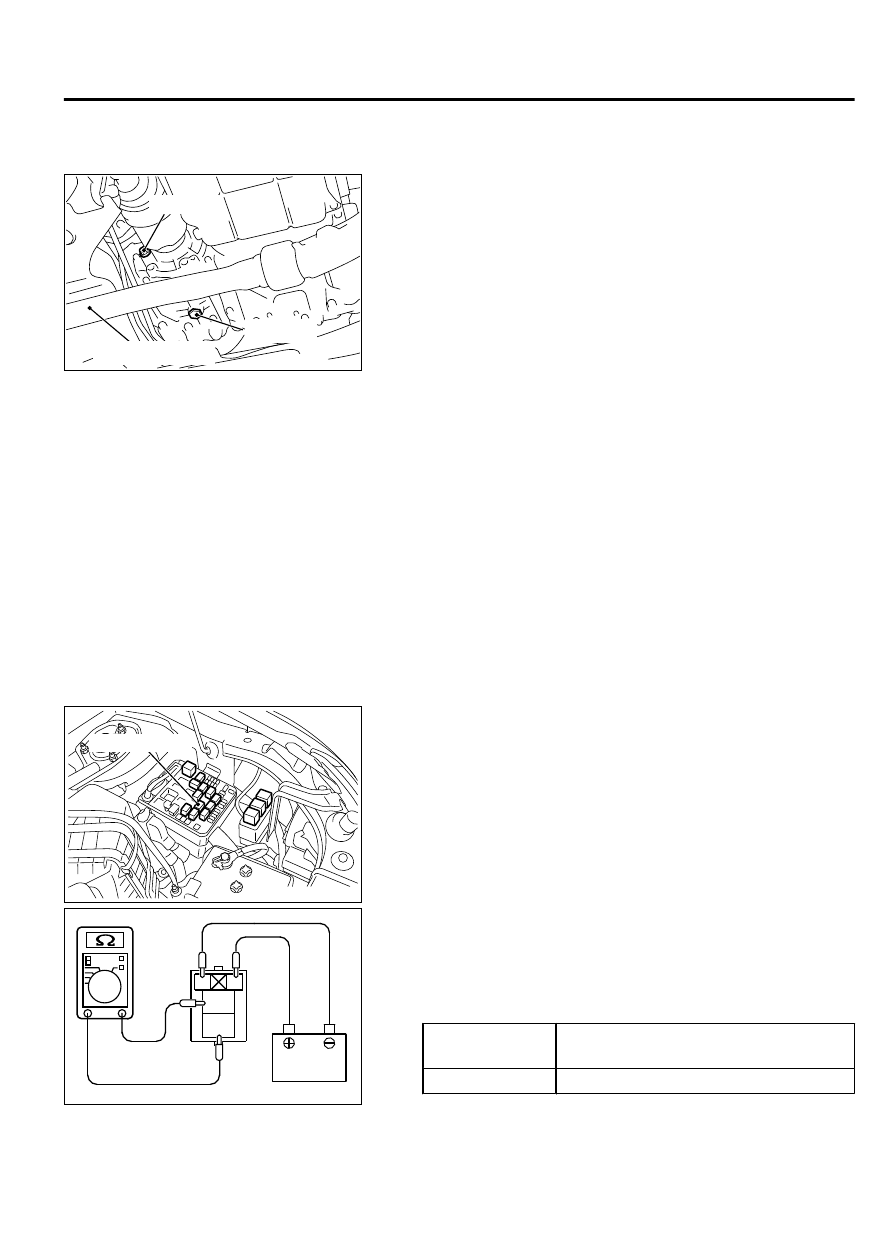
A/T CONTROL RELAY CHECK

M12301000093USA0000010000

ZC6028630001

A/T control relay

1.

Remove the A/T control relay.

ZC6028990000

4

1

2

3

2.

Use jumper wires to connect A/T control relay terminal No.1
to  the  negative  battery  terminal  and  terminal  No.2  to  the
positive battery terminal.

3.

Check for continuity between A/T control relay terminals No.3
and  No.4  when  the  jumper  wires  are  connected  to  and
disconnected from the battery.

Jumper wire

Continuity  between  terminals  No.3
and No.4

Connected

Continuity exists (2Ω or less)

AUTOMATIC TRANSAXLE MECHANICAL

23A-159

ON-VEHICLE SERVICE

Jumper wire

Continuity  between  terminals  No.3
and No.4

Disconnected

No continuity

4.

If there is any problem with the A/T control relay, replace it.

SOLENOID VALVE CHECK

M12301000094USA0000010000

ZC6038490000

16

10

7

19

13

1

12

18

6

3 4

2

20

14

8

15

21

9

5

11
17

22

A/T control solenoid valve
assembly connector

Battery tray

1.

Disconnect  the  A/T  control  solenoid  valve  assembly
connector.

2.

Measure  the  resistance  between  the  terminals  of  the
applicable solenoid valves and the ground.

Standard value:

Terminal No. Applicable  solenoid

valve

Resistanc
e value Ω

1

Low  clutch  linear
solenoid valve

Approxim
ately

 5.3

{Transmis
sion  fluid
temperatu
re:

 20°C

(68°F)}

4

Lock-up  and  low
reverse  brake  linear
solenoid valve

6

2-6

 brake

 linear

solenoid valve

9

Line  pressure  linear
solenoid valve

14

3-5  reverse  clutch
linear solenoid valve

19

High  clutch  linear
solenoid valve

17

Low-reverse

 brake

shift solenoid valve

Approxim
ately

 28

{Transmis
sion  fluid
temperatu
re:

 20°C

(68°F)}

22

Low

 clutch

 shift

solenoid valve

3.

When the resistance is within the standard value, check the
power supply and the ground circuits.

Each solenoid valve cannot be removed or replaced as a
single unit. When replacement of any one of the solenoid
valves is necessary, replace the valve body assembly.

4.

When the resistance is outside the standard value, replace the
valve body assembly and the harness.

23A-160

AUTOMATIC TRANSAXLE MECHANICAL

ON-VEHICLE SERVICE

TRANSMISSION FLUID TEMPERATURE SENSOR

CHECK

M12301000384USA0000010000

1.

Disconnect  the  A/T  control  solenoid  valve  assembly
connector.

ZC6038490000

16

10

7

19

13

1

12

18

6

3 4

2

20

14

8

15

21

9

5

11
17

22

A/T control solenoid valve
assembly connector

Battery tray

2.

Measure the resistance between the sensor-side connector
terminal  No.  2  of  the  A/T  control  solenoid  valve  assembly
connector and the ground.

Standard value:

Fluid temperature °
C (°F)

Resistance kΩ

10 (50)

Approx. 6.62

25 (77)

Approx. 3.51

80 (176)

Approx. 0.55

110 (230)

Approx. 0.25

NOTE: 

In the information screen on the multi-information

display, the fluid temperature warning comes on when the
transmission fluid temperature is approximately 140°C
(284 °F) or higher, and automatically goes out when the
A/T fluid temperature dropped below approximately 135°C
(275°F).

The  A/T  fluid  temperature  sensor  cannot  be  removed  or
replaced as a single unit. When the A/T fluid temperature
sensor  needs  to  be  replaced,  replace  the  valve  body
assembly.

3.

When  the  resistance  of  the  transmission  fluid  temperature
sensor is outside the standard value, and the fluid temperature
warning  comes  on/goes  out  at  other  than  the  specified
temperatures,  replace  the  valve  body  assembly  and  the
harness.

PADDLE SHIFT SWITCH CHECK

M12301000385USA0000010000

ZC6017740000

Paddle shift lever

1.

After operating the paddle shift levers (+ side, - side) by pulling
them to the rearward of the vehicle, check that the levers are
returned to the original positions quickly when released. Also,
check that no looseness, friction or abnormal sound occurs.

2.

Remove  the  paddle  shift  assembly.  (Refer  to  GROUP  37  -
Steering shaft P.37-23.)

AUTOMATIC TRANSAXLE MECHANICAL

23A-161

ON-VEHICLE SERVICE

ZC6017870000

3.

Check for continuity between the paddle shift switch connector
terminals.

Standard value:

Paddle shift lever

Terminal
number

Resistance
value

Upshift and hold the
lever.

1 - 2

Continuity
exists.  (2  Ω
or less)

Downshift  and  hold
the lever.

2 - 3

No operation

No continuity between the
terminals

4.

In  the  cases  other  than  the  above,  replace  the  paddle  shift
assembly.

SELECTOR LEVER OPERATION CHECK

M12301000013USA0000010001

1.

Pull the parking brake lever.

ZC6017600000

Turn the ignition switch to the   

   "ON" position, and operate the lever  
   while depressing the brake pedal.

Only shifting

Automatic return

2.

Move the selector lever to every range and check that the lever
moves smoothly with secure feel of engagement.

3.

Make sure that the engine starts when the selector lever is in
the "N" or "P" range, and does not start when the selector lever
is in other range.

4.

Start the engine. Release the parking brake lever.

5.

Make sure that the vehicle moves forward when the selector
lever is moved from the "N" range to "D" range, or to the 1st
to 6th speed in the sport mode. Also make sure that the vehicle
moves backward when the selector lever is moved from the
"N" to "R" range.

6.

Stop the engine.

7.

Turn ON the ignition switch, and move the selector lever from
the "P" to "R" range. Check that the backup light comes on
and the tone alarm sounds at this time.

NOTE: 

Since the vehicle is equipped with the A/T wrong-

operation preventive device, the selector lever cannot be
moved out of the "P" position without depressing the brake
pedal after turning "ON" the ignition switch.

KEY INTERLOCK MECHANISM CHECK/

ADJUSTMENT

M12301000313USA0000010000

1.

Carry out the following check.

23A-162

AUTOMATIC TRANSAXLE MECHANICAL

ON-VEHICLE SERVICE


Content   ..  509  510  511  512   ..