Mitsubishi Outlander XL. Manual - part 469


  Index      Mitsubishi     Mitsubishi Outlander XL - service repair manual 2007 year


Search            


Content   ..  467  468  469  470   ..


Mitsubishi Outlander XL. Manual - part 469


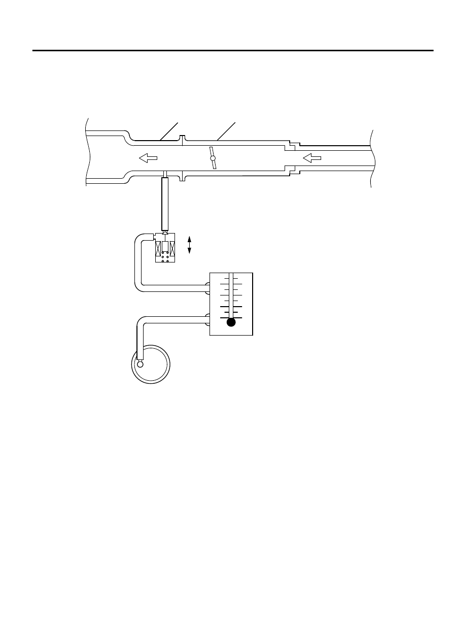
PURGE CONTROL SYSTEM CHECK (PURGE

FLOW CHECK)

M11703000014USA0000010000

ZK6000369

Throttle body

Intake manifold

From
aircleaner

To combustion
chamber

AA00

OFF

ON

Evaporative emission 
purge solenoid
(ON: Open)

Purge flow
indicator
(MB995061)

Purge hose

Evaporative
emission canister

Required Special Tool:

MB995061: Purge Flow Indicator

1.

Disconnect  the  purge  hose  from  the  evaporative  emission
(EVAP) purge solenoid, and connect special tool MB995061
between the EVAP purge solenoid and the purge hose.

2.

Before inspection, set the vehicle in the following conditions:

Engine coolant temperature: 80 - 95°C (176 - 203°F)

Lights, electric cooling fan and accessories: OFF

Transaxle: Neutral (P range on vehicles with A/T)

NOTE: 

Vehicles for Canada, the headlight, taillight,

etc. remain lit even when the lighting switch is in "OFF"
position but this is no problem for checks.

3.

Run the engine at idle for more than four minutes.

EMISSION CONTROL <MFI>

17c-11

EVAPORATIVE EMISSION CONTROL SYSTEM

4.

Check the purge flow volume when engine is revved suddenly
several times.

Standard value: Momentarily 20 cm3/s (2.5 SCFH) or
more.

5.

If the purge flow volume is less than the standard value, check
it again with the vacuum hose disconnected from the EVAP
canister. If the purge flow volume is less than the standard
value,  check  the  vacuum  port  and  the  vacuum  hose  for
clogging. Also check the EVAP purge solenoid. If the purge
flow  volume  is  at  the  standard  value,  replace  the  EVAP
canister.

EVAPORATIVE EMISSION PURGE SOLENOID

CHECK

M11703000017USA0000010000

1.

Disconnect the vacuum hose (black, black with red paint mark)
from the evaporative emission (EVAP) purge solenoid.

NOTE: 

When disconnecting the vacuum hose, always place

an identification mark so that it can be reconnected at
its original position.

2.

Disconnect the harness connector.

ZK600381AA00

A

B

3.

Connect a hand vacuum pump to nipple (A) of the EVAP purge
solenoid (refer to the illustration at left).

4.

As  described  in  the  chart  below,  check  airtightness  by
applying  a  vacuum  with  voltage  applied  directly  from  the
battery to the EVAP purge solenoid valve and without applying
voltage.

BATTERY

 POSITIVE

VOLTAGE

NORMAL CONDITION

Applied

Vacuum leaks

Not applied

Vacuum maintained

ZK600383AA00

5.

Measure the resistance between the terminals of the EVAP
purge solenoid.

Standard value: 22 - 26 ohms [at 20°C (68°F)]

6.

Replace the solenoid if resistance is out of specification.

MASS AIRFLOW SENSOR CHECK

M11703000504USA0000010000

To  inspect  these  parts,  refer  to  GROUP  13A,  Multiport  Fuel
Injection  (MFI)  -  Multiport  Fuel  Injection  (MFI)  Diagnosis  -
Diagnostic Trouble Code Chart P.13Ab-44.

17c-12

EMISSION CONTROL <MFI>

EVAPORATIVE EMISSION CONTROL SYSTEM

BAROMETRIC PRESSURE SENSOR CHECK

M11703000080USA0000010000

To  inspect  the  sensor,  refer  to  GROUP  13A,  Multiport  Fuel
Injection  (MFI)  -  Multiport  Fuel  Injection  (MFI)  Diagnosis  -
Diagnostic Trouble Code Chart P.13Ab-44.

ENGINE COOLANT TEMPERATURE SENSOR

CHECK

M11703000081USA0000010000

To  inspect  the  sensor,  refer  to  GROUP  13A,  Multiport  Fuel
Injection  (MFI)  -  Multiport  Fuel  Injection  (MFI)  Diagnosis  -
Diagnostic Trouble Code Chart P.13Ab-44.

INTAKE AIR TEMPERATURE SENSOR CHECK

M11703000082USA0000010000

To  inspect  the  sensor,  refer  to  GROUP  13A,  Multiport  Fuel
Injection  (MFI)  -  Multiport  Fuel  Injection  (MFI)  Diagnosis  -
Diagnostic Trouble Code Chart P.13Ab-44.

FUEL TANK DIFFERENTIAL PRESSURE SENSOR

CHECK

M11703000077USA0000010000

To inspect the sensor, refer to GROUP 13B, Fuel Supply - Fuel
Tank - Fuel Tank Inspection - Fuel Tank Differential Pressure
Sensor Check P.13B-25.

EVAPORATIVE EMISSION VENTILATION

SOLENOID CHECK

M11703000078USA0000010000

Refer to Emission Control - Evaporative Emission Canister and
Fuel  Tank  Pressure  Relief  Valve  -  Inspection  -  Evaporative
Emission Ventilation Solenoid Check P.17c-19.

EXHAUST GAS RECIRCULATION (EGR) SYSTEM

GENERAL INFORMATION (EXHAUST GAS RECIRCULATION SYSTEM)

M11703000052USA0000010000

The exhaust gas recirculation system (EGR) lowers
the nitrogen oxides (NOx) emission level. When the
air/fuel  mixture  combustion  temperature  is  high,  a
large quantity of NOx is generated in the combustion
chamber. Therefore, this system recirculates part of
exhaust gas from the exhaust port of the cylinder head
to  the  combustion  chamber  through  the  intake
manifold to decrease the air/fuel mixture combustion
temperature, resulting in reduction of NOx. The EGR

flow  rate  is  controlled  by  the  EGR  valve  (Stepper
Motor) for driveability quality.

OPERATION

When  the  engine  coolant  temperature  is  low,  when
the  engine  is  at  idle  or  when  a  wide  open  throttle
operation  is  performed,  the  EGR  valve  (Stepper
Motor)  is  kept  closed,  achieving  no  EGR.  After
warming  up  the  engine,  the  EGR  valve  (Stepper
Motor) can be opened by the engine control module
(ECM).

EMISSION CONTROL <MFI>

17c-13

EVAPORATIVE EMISSION CONTROL SYSTEM

The ECM monitors the EGR system and illuminates
the Malfunction Indicator Lamp (SERVICE ENGINE

SOON or Check Engine Lamp) to indicate that there
is a malfunction.

SYSTEM DIAGRAM

ZK602754

 ECM

Mass airflow sensor

Intake air temperature
sensor

Engine coolant
temperature sensor

Throttle position sensor

Crankshaft position sensor

Manifold absolute
pressure sensor

Battery

AA00

EGR valve
(stepper moter)

COMPONENT LOCATION

M11703000076USA0000010000

ZK600384

Exhaust gas recirculation valve

AA00

EGR VALVE (STEPPER MOTOR) CHECK

M11703000502USA0000010000

Required Special Tool:

MB991658: Test Harness Set

Checking the Operation Sound

1.

Check that the operation sound of the stepper motor can be
heard from the EGR valve when the ignition switch is turned
ON (without starting the engine).

2.

If  the  operation  sound  cannot  be  heard,  inspect  the  drive
circuit of the stepper motor.

17c-14

EMISSION CONTROL <MFI>

EXHAUST GAS RECIRCULATION (EGR) SYSTEM


Content   ..  467  468  469  470   ..