Mitsubishi Outlander XL. Manual - part 470


  Index      Mitsubishi     Mitsubishi Outlander XL - service repair manual 2007 year


Search            


Content   ..  468  469  470  471   ..


Mitsubishi Outlander XL. Manual - part 470


NOTE: 

If the operation sound is not heard, and the circuit

is normal, either the stepper motor or the ECM or PCM may
have failed.

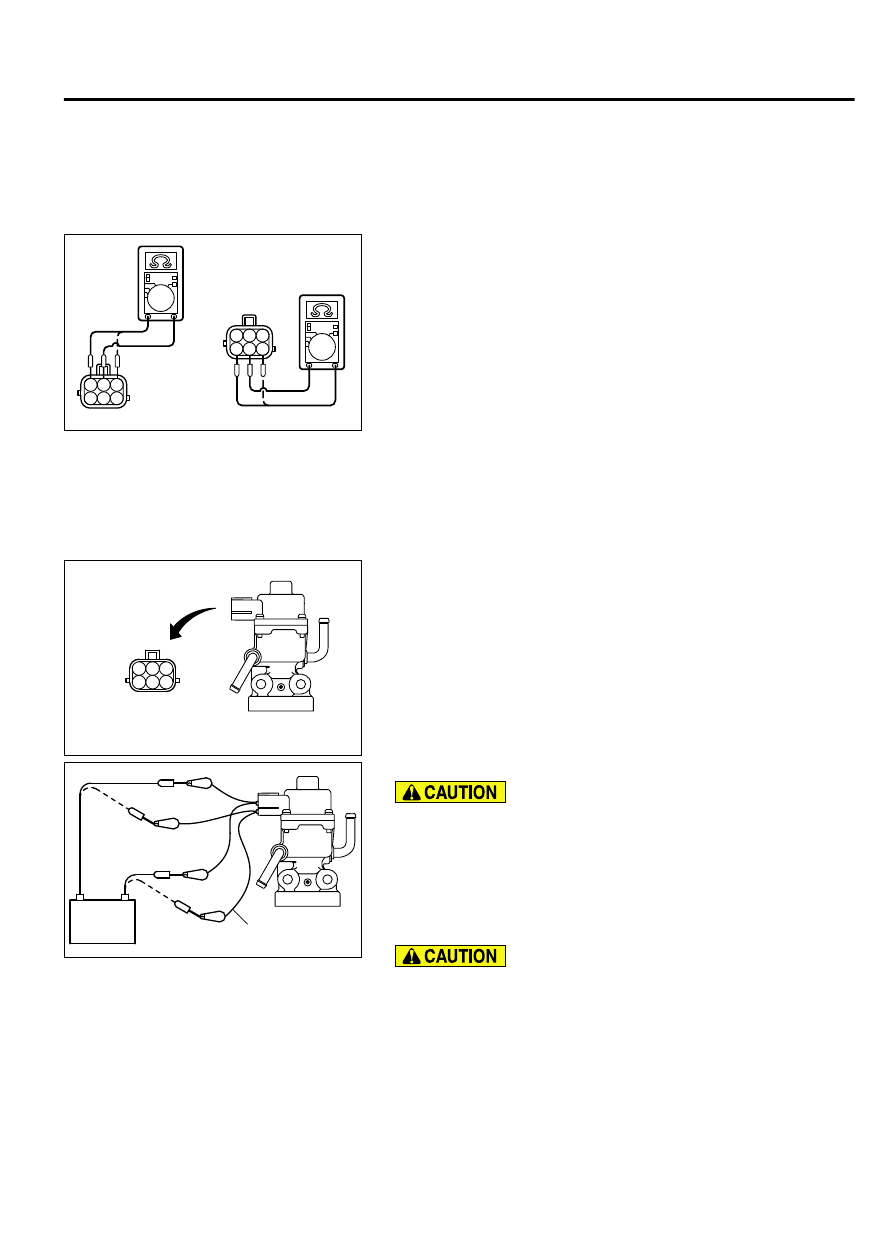
Checking the Coil Resistance

ZK600385

1 2 3
4 5 6

1 2 3
4 5 6

AA00

1.

Remove the EGR valve.

2.

Measure  the  resistance  between  terminal  No.  2  and  either
terminal No. 1 or terminal No. 3 of the connector at the EGR
valve.

Standard value: 20 - 24 Ω [at 20°C (68°F)]

3.

If the resistance is not within the standard, replace the EGR
valve.

4.

Measure  the  resistance  between  terminal  No.  5  and  either
terminal No. 6 or terminal No. 4 of the connector at the EGR
valve.

Standard value: 20 - 24 Ω [at 20°C (68°F)]

5.

If the resistance is not within the standard, replace the EGR
valve.

Operation Check

1.

Remove the EGR valve.

ZK600386

1 2 3
4 5 6

AA00

EGR valve

2.

Connect special tool MB991658 to the EGR valve.

ZK600387

MB991658

Battery

AA00

3.

Connect the battery positive (+) terminal to terminal No. 2.

Connecting battery voltage to the EGR valve for a long time
could damage the coil.

4.

Connect terminals 1 and 3 to the negative (-) terminal of the
battery,  in  order  to  test  whether  the  stepper  motor  vibrates
(with  a  slight  shudder),  indicating  that  the  stepper  motor  is
operating.

5.

Connect the battery positive (+) terminal to terminal No. 5.

Connecting battery voltage to the EGR valve for a long time
could damage the coil.

6.

Connect terminals 4 and 6 to the negative (-) terminal of the
battery,  in  order  to  test  whether  the  stepper  motor  vibrates
(with  a  slight  shudder),  indicating  that  the  stepper  motor  is
operating.

EMISSION CONTROL <MFI>

17c-15

EXHAUST GAS RECIRCULATION (EGR) SYSTEM

7.

If vibrations can be felt as a result of the test, the stepper motor
is determined to be normal.

EGR VALVE (STEPPER MOTOR) CLEANING

M11703000503USA0000010000

NOTE: 

DO not use solvents or other cleaning agents, which

will enter the motor and cause a malfunction.
Remove the EGR valve and make sure that it is not stuck and
does  not  have  any  carbon  deposits.  If  there  are  any  carbon
deposits, use a wire brush to clean it.

MASS AIRFLOW SENSOR CHECK

M11703000504USA0000010001

To  inspect  these  parts,  refer  to  GROUP  13A,  Multiport  Fuel
Injection  (MFI)  -  Multiport  Fuel  Injection  (MFI)  Diagnosis  -
Diagnostic Trouble Code Chart P.13Ab-44.

ENGINE COOLANT TEMPERATURE SENSOR

CHECK

M11703000081USA0000010001

To  inspect  the  sensor,  refer  to  GROUP  13A,  Multiport  Fuel
Injection  (MFI)  -  Multiport  Fuel  Injection  (MFI)  Diagnosis  -
Diagnostic Trouble Code Chart P.13Ab-44.

CRANKSHAFT POSITION SENSOR CHECK

M11703000083USA0000010000

To  inspect  the  sensor,  refer  to  GROUP  13A,  Multiport  Fuel
Injection  (MFI)  Multiport  Fuel  Injection  (MFI)  Diagnosis  -
Diagnostic Trouble Code Chart P.13Ab-44.

REMOVAL AND INSTALLATION

M11703000105USA0000010000

Pre-removal and Post-installation Operation

Engine Coolant Draining and Refilling (Refer to GROUP 14, On-vehicle Service - Engine Coolant Replacement P.14-15).

Air Cleaner Intake Duct Removal and Installation (Refer to GROUP 15, Air Cleaner P.15-6).

17c-16

EMISSION CONTROL <MFI>

EXHAUST GAS RECIRCULATION (EGR) SYSTEM

ZC6020680000

1

2

3

4

5

N

23 ± 6 N·m
17 ± 4 ft-lb

Removal steps

1.

EGR valve connector

2.

Water hose

3.

Water hose

Removal steps

4.

EGR valve

5.

EGR valve gasket

EMISSION CONTROL <MFI>

17c-17

EVAPORATIVE EMISSION CANISTER AND FUEL TANK PRESSURE RELIEF VALVE

EVAPORATIVE EMISSION CANISTER AND FUEL TANK PRESSURE RELIEF VALVE

REMOVAL AND INSTALLATION

M11703000048USA0000010000

ZC602420

1

2

3

4

5

6

7

8

11

12

9

10

AA00

11 ± 2 N·m
98 ± 17 in-lb

12 ± 3 N·m
107 ± 26 in-lb

4.5 ± 1.5 N·m
39 ± 13 in-lb

11 ± 2 N·m
98 ± 17 in-lb

5.5 ± 1.5 N·m
49 ± 13 in-lb

11 ± 2 N·m
98 ± 17 in-lb

14

13

4.5 ± 1.5 N·m
39 ± 13 in-lb

4.5 ± 1.5 N·m
39 ± 13 in-lb

Removal steps

1. Evaporative emission canister protector
2. Evaporative

 emission

 ventilation

solenoid connector

3. Fuel vapor tube assembly
4. Fuel purge pipe assembly connection
5. Vent hose A connection
6. Evaporative  emission  canister  and

bracket assembly

7. Evaporative emission canister bracket
8. Evaporative  emission  canister  and

evaporative emission ventilation solenoid
assembly

9. Vent hose A

Removal steps

10
.

Vent hose B connection

11
.

Air filter

12
.

Air filter bracket

·

Rear axle drive shaft (LH) <AWD> (Refer
to GROUP 27B, Drive Shaft Assembly P.
27B-19)

13
.

Vent hose B

14
.

Vent pipe

17c-18

EMISSION CONTROL <MFI>

EVAPORATIVE EMISSION CANISTER AND FUEL TANK PRESSURE RELIEF VALVE


Content   ..  468  469  470  471   ..