Mitsubishi Outlander XL. Manual - part 454
ZC6018520000
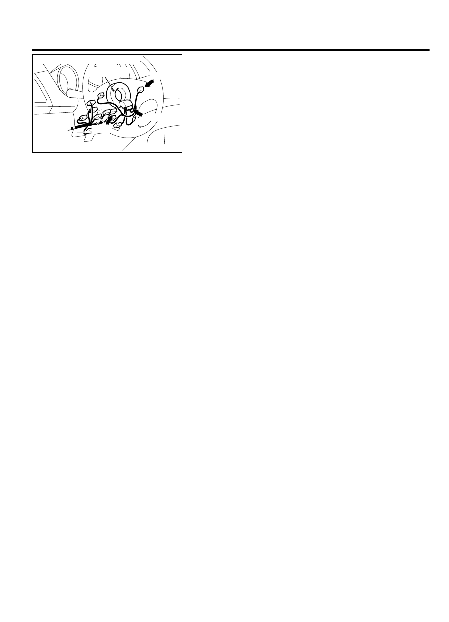
C-201 (L)
C-204
C-202
Connectors: C-201, C-202, C-204
Clock spring
CIRCUIT OPERATION
This circuit judges the signals of each switch ("ON/
OFF", "CANCEL", "COAST/SET" and "ACC/RES") of
the auto-cruise control switch. The ECM detects the
state of the auto-cruise control switch by sensing the
voltages shown below.
⦆
When all switches are OFF: 4.7 - 5.0 volts
⦆
When the "ON/OFF" switch is "ON": 0 - 0.5 volt
⦆
When the "CANCEL" switch is "ON": 1.0 - 1.8 volts
⦆
When the "COAST/SET" switch is "ON": 2.3 - 3.0
volts
⦆
When the "ACC/RES" switch is "ON": 3.5 - 4.2 volts
DTC SET CONDITIONS
Check Condition
⦆
The "CRUISE" indicator light illuminates.
Judgement Criteria
⦆
This DTC will be set when the "COAST/SET" switch
or the "ACC/RES" switch is continuously ON foe 60
seconds or more.
TROUBLESHOOTING HINTS (The most likely
causes for this case:)
⦆
Malfunction of the auto-cruise control switch.
⦆
Malfunction of the clock spring.
⦆
Damaged harness or connector.
⦆
Malfunction of the ECM.
DIAGNOSIS
Required Special Tools:
⦆
MB991958: Scan Tool (M.U.T.-III Sub Assembly)
⦆
MB991824: V.C.I.
⦆
MB991827: M.U.T.-III USB Cable
⦆
MB991910: M.U.T.-III Main Harness A
⦆
MB991223: Harness Set
⦆
MB992006: Extra Fine Probe
⦆
MB992110: Power Plant ECU Check Harness
AUTO-CRUISE CONTROL SYSTEM
17b-9
AUTO-CRUISE CONTROL SYSTEM DIAGNOSIS