Mitsubishi Outlander XL. Manual - part 436


  Index      Mitsubishi     Mitsubishi Outlander XL - service repair manual 2007 year


Search            


Content   ..  434  435  436  437   ..


Mitsubishi Outlander XL. Manual - part 436


STEP 3. Check the hanger for cracks.

Q:Is the hanger cracked?

YES:

 Replace, then go to Step 1.

NO:

 Go to Step 4.

STEP 4. Check for interference of the pipes and
muffler with the body.

Q:Are  the  pipes  and  muffler  interfering  with  the

body?

YES:

 Repair, then go to Step 1.

NO:

 Go to Step 5.

STEP 5. Check the heat protectors.

Q:Are any heat protectors loose or damaged?

YES:

 Tighten or replace, then go to Step 1.

NO:

 Go to Step 6.

STEP 6. Check the pipes and muffler for damage.

Q:Are the pipes and muffler damaged?

YES:

 Replace, then go to Step 1.

NO:

 There is no action to be taken.
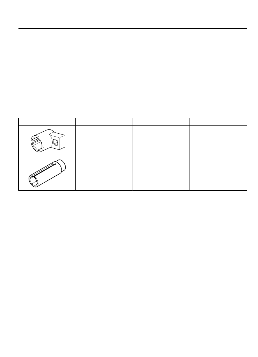
SPECIAL TOOLS

M11501000006USA0000010000

Tool

Tool number and name Supersession

Application

YB991953AA01

MB991953
Oxygen sensor wrench

MB991953-01

Removal  and  installation
of heated oxygen sensor

YD998770AA01

MD998770
Oxygen sensor wrench

MD998770-01 or General
service tool

INTAKE AND EXHAUST

15-5

SPECIAL TOOLS

AIR CLEANER

REMOVAL AND INSTALLATION

M11501000021USA0000010000

ZC600332

1

2

3

4

5

7

8

9

10

3.9 ± 1.0 N·m
35 ± 8 in-lb

3.9 ± 1.0 N·m
35 ± 8 in-lb

9.5 ± 3.5 N·m
84 ± 31 in-lb

9.5 ± 3.5 N·m
84 ± 31 in-lb

7.0 ± 3.0 N·m
62 ± 27 in-lb

1.8 ± 0.6 N·m
16 ± 5 in-lb

6

AA00

Removal steps

1.

Air cleaner intake duct

2.

Mass airflow sensor connector

3.

Mass airflow sensor

4.

Air cleaner body

5.

Air cleaner element

6.

Breather hose connection

>>A<<

7.

Nipple

Removal steps

8.

Air cleaner to throttle body duct

·

Engine control module (ECM) [Refer to
GROUP 13Aa, Engine Control Module
(ECM) P.13Aa-37].

9.

Air cleaner cover

10. Air cleaner bracket


INSTALLATION SERVICE POINT

>>A<< NIPPLE INSTALLATION

Securely install the nipple to the air cleaner to throttle body
duct.

15-6

INTAKE AND EXHAUST

AIR CLEANER

INTAKE MANIFOLD PLENUM

REMOVAL AND INSTALLATION

M11501000027USA0000010000

Pre-removal Operation

Engine  Coolant  Draining  (Refer  to  GROUP  14,  On-vehicle

Service P.14-15).

Engine Cover Removal (Refer to GROUP 16c, Ignition coil P.

16c-6).

Strut Tower Bar Removal (Refer to GROUP 42Aa, Strut Tower

Bar P.42Aa-11).

Air Cleaner Assembly Removal (Refer to P.15-6).

Throttle  Body  Removal  (Refer  to  GROUP  13Aa,  Throttle

Body P.13Aa-36).

Post-installation Operation

Throttle  Body  Installation  (Refer  to  GROUP  13Aa,  Throttle

Body P.13Aa-36).

Air Cleaner Assembly Installation (Refer to P.15-6).

Strut  Tower  Bar  Installation  (Refer  to  GROUP  42Aa,  Strut

Tower Bar P.42Aa-11).

Engine  Cover  Installation  (Refer  to  GROUP  16c,  Ignition

coil P.16c-6).

Engine  Coolant  Refilling  (Refer  to  GROUP  14,  On-vehicle

Service P.14-15).

ZC600581

9.5 ± 2.5 N·m
84 ± 22 in-lb

22 ± 1 N·m
16 ± 1 ft-lb

22 ± 1 N·m
16 ± 1 ft-lb

11 ± 1 N·m
98 ± 8 in-lb

11 ± 1 N·m
98 ± 8 in-lb

11 ± 1 N·m
98 ± 8 in-lb

11 ± 1 N·m
98 ± 8 in-lb

9.5 ± 2.5 N·m
84 ± 22 in-lb

9.5 ± 2.5 N·m
84 ± 22 in-lb

20 ± 5 N·m
15 ± 3 ft-lb

20 ± 5 N·m
15 ± 3 ft-lb

20 ± 5 N·m
15 ± 3 ft-lb

20 ± 5 N·m
15 ± 3 ft-lb

20 ± 5 N·m
15 ± 3 ft-lb

5.5 ± 1.5 N·m
49 ± 13 in-lb

22 ± 1 N·m
16 ± 1 ft-lb

3

2

1

4

5

6

7

8

9

10

11

12

13

14

15

16

17

18

19

20

20

21

22

23

24

25

26

27

29

30

31

28

32

33

34

35

35

N

N

N

N

5.0 ± 1.0 N·m
44 ± 9 in-lb

AA00

Removal steps

1.

Manifold  absolute  pressure  sensor
connector

Removal steps

2.

Manifold absolute pressure sensor

3.

O-ring

INTAKE AND EXHAUST

15-7

INTAKE MANIFOLD PLENUM

Removal steps

4.

Variable  intake  air  control  solenoid
valve connector

5.

Right  bank  heated  oxygen  sensor
connector

6.

Right  bank  heated  oxygen  sensor
(Rear)

7.

Right  bank  heated  oxygen  sensor
(Front)

8.

Purge hose

9.

Vacuum hose assembly

10. Vacuum hose
11. Vacuum tank
12. Vacuum tank bracket
13. Variable  intake  air  control  solenoid

valve

14. Left bank knock sensor connector
15. Left bank knock sensor
16. Right bank knock sensor connector
17. Right bank knock sensor
18. Control  wiring  harness  and  injector

wiring harness combination connector

Removal steps

19. Control wiring harness
20. Engine cover bracket
21. Harness bracket
22. Vacuum hose connection
23. Evaporative  emission  purge  solenoid

connector

24. Purge hose
25. Purge hose
26. Intake manifold plenum stay, rear
27. Evaporative emission purge solenoid
28. Intake manifold plenum stay, front
29. Exhaust gas recirculation pipe
30. Gasket
31. Gasket
32. Blow-by hose connection
33. Intake manifold plenum
34. Intake manifold plenum gasket
35. Harness bracket

INTAKE MANIFOLD

REMOVAL AND INSTALLATION

M11501000030USA0000010000

Pre-removal Operation

Fuel  Discharge  Prevention  [Refer  to  GROUP  13Aa,  On-vehicle

Service  -  Fuel  Pump  Connector  Disconnection  (How  to  Reduce

Pressurized Fuel Lines) P.13Aa-20].

Intake Manifold Plenum Removal (Refer to P.15-7).

Post-installation Operation

Intake Manifold Plenum Installation (Refer to P.15-7).

Fuel Leakage Inspection

15-8

INTAKE AND EXHAUST

INTAKE MANIFOLD


Content   ..  434  435  436  437   ..