Mitsubishi Outlander XL. Manual - part 359
MONITOR EXECUTION
Continuous
MONITOR EXECUTION CONDITIONS (Other
monitor and Sensor)
Other Monitor (There is no temporary DTC stored in
memory for the item monitored below)
⦆
Not applicable
Sensor (The sensor below is determined to be
normal)
⦆
Not applicable
DTC SET CONDITIONS
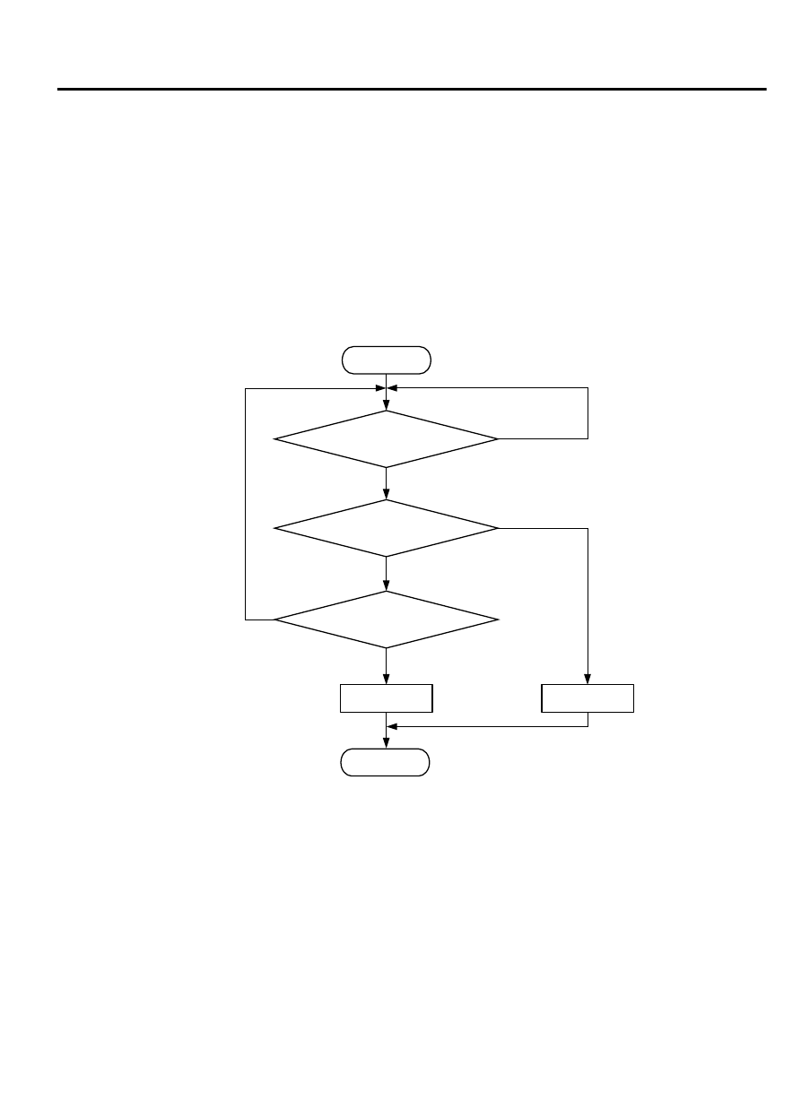
Logic Flow Chart
ZK604062 AA00
Start
End
No
No
Yes
Yes
Yes
No
Malfunction
Good
Continuous failure
for specfied time
|Ec-calculated Ec|
> 33%
Monitoring
conditions
Ec: load valve
Check Conditions
⦆
The difference between the actual volumetric
efficiency and the volumetric efficiency estimated
by the (sub) throttle position sensor is 0 % or more.
Or, the volumetric efficiency is 60 % or less.
⦆
The engine speed is between 750 and 3000r/min.
Or, the (sub) throttle position sensor output voltage
is 3 volts or more.
Judgment Criterion
⦆
For 0.4 second, the difference between the actual
volumetric efficiency and the volumetric efficiency
estimated by the (sub) throttle position sensor is 33
% or more.
MULTIPORT INJECTION SYSTEM (MFI) <DIAGNOSIS>
13Ab-631
DIAGNOSTIC TROUBLE CODE PROCEDURES