Mitsubishi Outlander XL. Manual - part 357
⦆
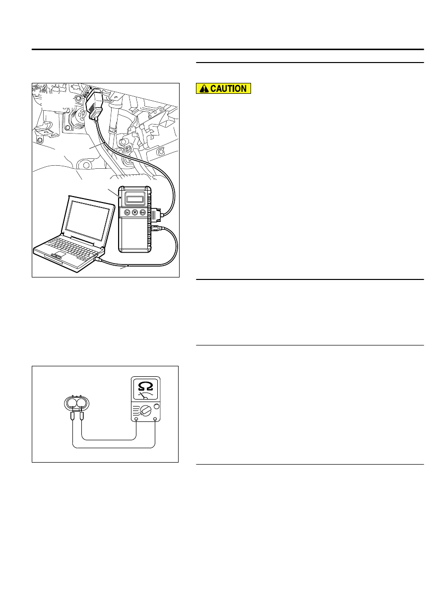
MB991910: Main Harness A
STEP 1. Using scan tool MB991958, check data item 98: Oil
control valve.
ZC501967
AC404789
ZC5019680000
MB991824
MB991827
MB991910
Data link
connector
To prevent damage to scan tool MB991958, always turn the
ignition switch to the "LOCK" (OFF) position before
connecting or disconnecting scan tool MB991958.
(1)
Connect scan tool MB991958 to the data link connector.
(2)
Turn the ignition switch to the "ON" position.
(3)
Set scan tool MB991958 to the data reading mode for item
98, Engine oil control valve.
⦆
An operation sound should be heard and vibration should
be felt when the right bank engine oil control valve is
operated.
(4)
Turn the ignition switch to the "LOCK" (OFF) position.
Q:Is the engine oil control valve operating properly?
YES:
It can be assumed that this malfunction is
intermittent. Refer to GROUP 00, How to Use
Troubleshooting/Inspection Service Points - How to Cope
with Intermittent Malfunctions P.00-15.
NO:
Then go to Step 2.
STEP 2. Check harness connector B-106 engine oil control
valve and harness connector B-10 at ECM for damage.
Q:Is the harness connector in good condition?
YES:
Go to Step 3.
NO:
Repair or replace it. Refer to GROUP 00E, Harness
Connector Inspection P.00E-2. Then go to Step 7.
STEP 3. Check the right bank engine oil control valve.
(1)
Disconnect the engine oil control valve connector B-106.
ZK603276AA00
1
2
Engine oil control
valve connector
(2)
Measure the resistance between engine oil control valve side
connector terminal No. 1 and No. 2.
Standard value: 6.9 - 7.9 Ω [at 20°C (68°F)]
Q:Is the measured resistance between 6.9 and 7.9 ohms [at
20°C (68°F)]?
YES:
Go to Step 4.
NO:
Replace the right bank engine oil control valve. Then
go to Step 7.
STEP 4. Measure the power supply voltage at right bank
engine oil control valve harness side connector B-106.
(1)
Disconnect the connector B-106 and measure at the harness
side.
(2)
Turn the ignition switch to the "ON" position.
MULTIPORT INJECTION SYSTEM (MFI) <DIAGNOSIS>
13Ab-623
DIAGNOSTIC TROUBLE CODE PROCEDURES