Mitsubishi Outlander XL. Manual - part 355


  Index      Mitsubishi     Mitsubishi Outlander XL - service repair manual 2007 year


Search            


Content   ..  353  354  355  356   ..


Mitsubishi Outlander XL. Manual - part 355


Judgment Criterion

Engine  oil  pressure  switch  has  been  ON  for  5
seconds.

OBD-II DRIVE CYCLE PATTERN
Refer to Diagnostic Function - OBD-II Drive Cycle -
Pattern 21 P.13Ab-8.

TROUBLESHOOTING HINTS (The most likely
causes for this code to be set are:)

Connector damage.

Harness damage.

Engine oil pressure switch failed.

Engine oil control valve failed.

ECM failed.


DIAGNOSIS

Required Special Tools:

MB991958: Scan Tool (M.U.T.-III Sub Assembly)

MB991824: V.C.I.

MB991827: USB Cable

MB991910: Main Harness A

MB992110: Power Plant ECU Check Harness

STEP 1. Check harness connector B-106 at engine oil
pressure switch and harness connector B-10 at ECM for
damage.

Q:Is the harness connector in good condition?

YES:

 Go to Step 2.

NO:

 Repair or replace it. Refer to GROUP 00E, Harness

Connector Inspection P.00E-2. Then go to Step 8.

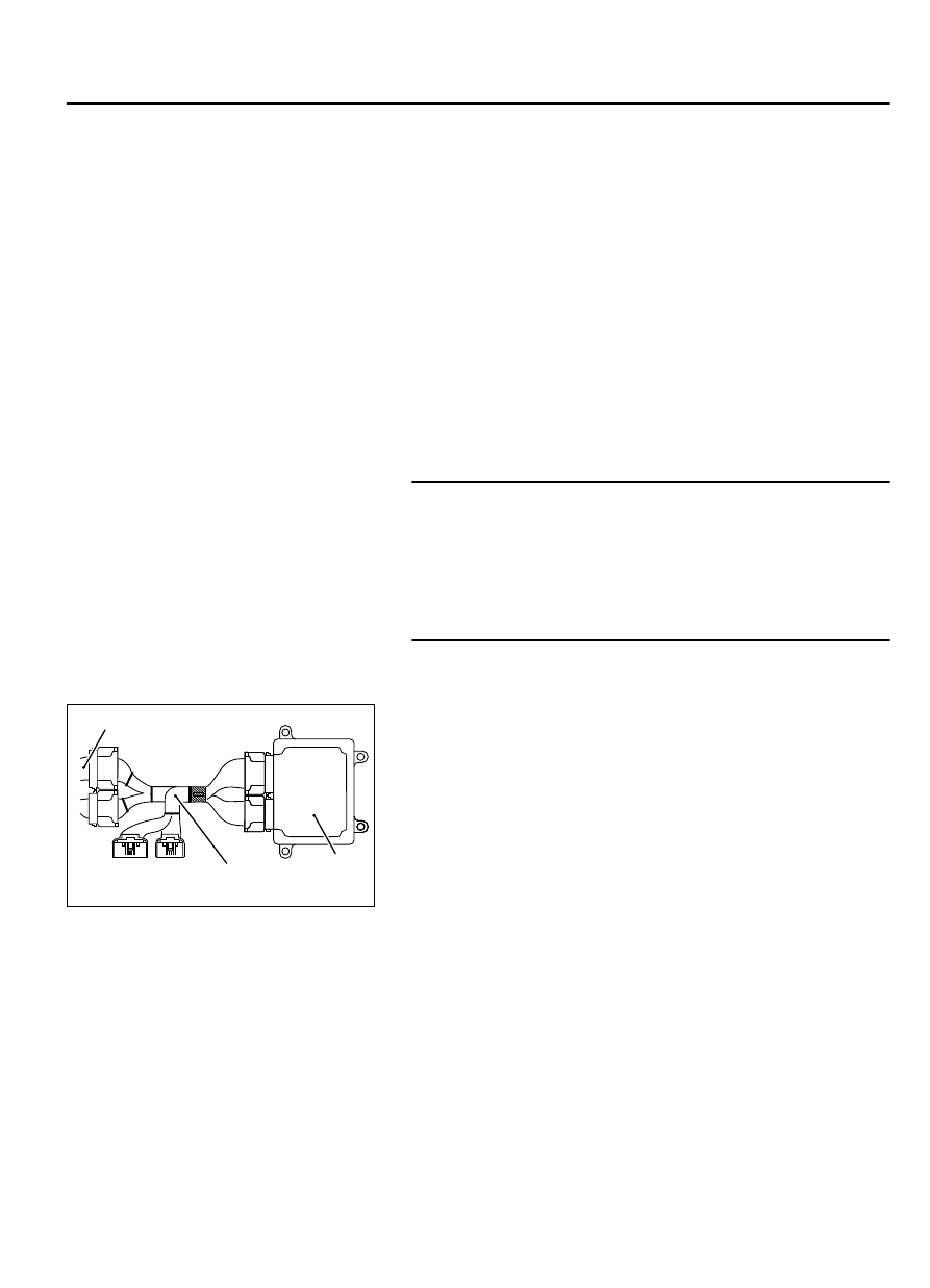
STEP 2. Measure the power supply voltage at ECM
connector B-10 by using power plant ECU check harness
special tool MB992110.

ECM

ZK603234AA00

Body side harness 

MB992110

(1)

Disconnect  all  ECM  connectors.  Connect  the  power  plant
ECU  check  harness  special  tool  MB992110  between  the
separated connectors.

(2)

Start the engine and run at idle.

MULTIPORT INJECTION SYSTEM (MFI) <DIAGNOSIS>

13Ab-615

DIAGNOSTIC TROUBLE CODE PROCEDURES

ZK603271

16 15 14 13 12 11 10 9 8 7 6 5 4 3

2

1

32 31 30 29 28 27 26 25 24 23 22 21 20 19 18 17

48 47 46 45 44 43 42 41 40 39 38 37 36 35 34 33

64 63 62 61 60 59 58 57 56 55 54 53 52 51 50 49

AA00

Special tool 64-pin 
connector:
component side 

(3)

Measure the voltage between terminal No. 7 and ground.

Voltage should be 1 volt or less when engine is idling.

Voltage  should  be  battery  positive  voltage  when  engine
speed is higher than 5,200 r/min.

(4)

Turn the ignition switch to the "LOCK" (OFF) position.

Q:Is the measured voltage normal?

YES:

 It can be assumed that this malfunction is

intermittent. Refer to GROUP 00, How to Use
Troubleshooting/Inspection Service Points - How to Cope
with Intermittent Malfunctions P.00-15.

NO:

 Go to Step 3.

STEP 3. Measure the power supply voltage at engine oil
pressure switch connector B-107.

(1)

Disconnect the connector B-107 and measure at the harness
side.

(2)

Turn the ignition switch to the "ON" position.

B-107 harness
connector:
component side 

ZK603272AA00

1

(3)

Measure the voltage between terminal No. 1 and ground.

Voltage should be battery positive voltage.

(4)

Turn the ignition switch to the "LOCK" (OFF) position.

Q:Is  battery  positive  voltage  (approximately  12  volts)

present?

YES:

 Go to Step 5.

NO:

 Go to Step 4.

STEP 4. Check for open circuit and short circuit to ground
between engine oil pressure switch connector B-107 and
ECM connector B-10.

(1)

Disconnect the connector B-107 and B-10 measure at the
harness side.

13Ab-616

MULTIPORT INJECTION SYSTEM (MFI) <DIAGNOSIS>

DIAGNOSTIC TROUBLE CODE PROCEDURES

16 15 14 13 12 11 10 9 8 7 6 5 4 3

2

1

32 31 30 29 28 27 26 25 24 23 22 21 20 19 18 17

48 47 46 45 44 43 42 41 40 39 38 37 36 35 34 33

64 63 62 61 60 59 58 57 56 55 54 53 52 51 50 49

ZK603273

1

B-10 harness
connector:
component side 

AA00

B-107 harness
connector:
component side 

(2)

Measure the resistance between connector B-107 (terminal
No. 1) and connector B-10 (terminal No. 7).

Should be less than 2 ohms.

B-107 harness
connector:
component side 

ZK603272AA00

1

(3)

Check for the continuity between connector B-107 (terminal
No. 1) and ground.

Not continuity.

Q:Is the harness wire in good condition?

YES:

 Replace the ECM. When the ECM is replaced, register

the ID code. Refer to GROUP 42B, ID Code Registration
Judgment Table <Vehicles with KOS> P.42B-12or GROUP
42C, ID Code Registration Judgment Table <Vehicles with
WCM> P.42C-8. Then go to Step 7.

NO:

 Repair it. Then go to Step 8.

STEP 5. Check for harness damage between engine oil
pressure switch connector B-107 and ECM connector B-10.

(1)

Disconnect the connector B-107 and B-10 measure at the
harness side.

MULTIPORT INJECTION SYSTEM (MFI) <DIAGNOSIS>

13Ab-617

DIAGNOSTIC TROUBLE CODE PROCEDURES

16 15 14 13 12 11 10 9 8 7 6 5 4 3

2

1

32 31 30 29 28 27 26 25 24 23 22 21 20 19 18 17

48 47 46 45 44 43 42 41 40 39 38 37 36 35 34 33

64 63 62 61 60 59 58 57 56 55 54 53 52 51 50 49

ZK603273

1

B-10 harness
connector:
component side 

AA00

B-107 harness
connector:
component side 

(2)

Measure the resistance between B-107 connector (terminal
No. 1) and B-10 (terminal No. 7) connector.

Should be less than 2 ohms.

Q:Is the measured resistance less than 2 ohms?

YES:

 Then go to Step 6.

NO:

 Repair it. Then go to Step 8.

STEP 6. Using scan tool MB991958, check data item 98: Oil
control valve.

ZC501967

AC404789

ZC5019680000

MB991824

MB991827

MB991910

Data link

connector

To prevent damage to scan tool MB991958, always turn the
ignition  switch  to  the  "LOCK"  (OFF)  position  before
connecting or disconnecting scan tool MB991958.

(1)

Connect scan tool MB991958 to the data link connector.

(2)

Turn the ignition switch to the "ON" position.

(3)

Set scan tool MB991958 to the data reading mode for item
98, Engine oil control valve.

An operation sound should be heard and vibration should
be  felt  when  the  right  bank  engine  oil  control  valve  is
operated.

(4)

Turn the ignition switch to the "LOCK" (OFF) position.

Q:Is  the  right  bank  engine  oil  control  valve  operating

properly?

YES:

 Then go to Step 7.

NO:

 Replace the engine oil control valve. Then go to Step

8.

STEP 7. Replace the engine oil pressure switch

(1)

Carry  out  test  drive  with  the  drive  cycle  pattern.  Refer  to
Diagnostic  Function  -  OBD-II  Drive  Cycle  -  Pattern  21  P.
13Ab-8.

(2)

Check the diagnostic trouble code (DTC).

Q:Is DTC P1020 set?

13Ab-618

MULTIPORT INJECTION SYSTEM (MFI) <DIAGNOSIS>

DIAGNOSTIC TROUBLE CODE PROCEDURES


Content   ..  353  354  355  356   ..