Mitsubishi Outlander XL. Manual - part 360
DIAGNOSIS
Required Special Tools:
⦆
MB991958: Scan Tool (M.U.T.-III Sub Assembly)
⦆
MB991824: V.C.I.
⦆
MB991827: USB Cable
⦆
MB991910: Main Harness A
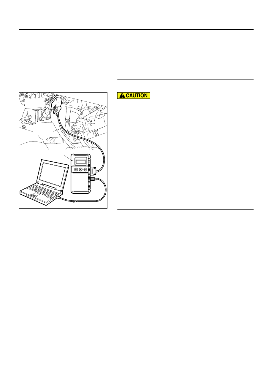
STEP 1. Using scan tool MB991958, read the diagnostic
trouble code (DTC).
ZC501967
AC404789
ZC5019680000
MB991824
MB991827
MB991910
Data link
connector
To prevent damage to scan tool MB991958, always turn the
ignition switch to the "LOCK" (OFF) position before
connecting or disconnecting scan tool MB991958.
(1)
Connect scan tool MB991958 to the data link connector.
(2)
Turn the ignition switch to the "ON" position.
(3)
Read the DTC.
(4)
Turn the ignition switch to the "LOCK" (OFF) position.
Q:Is the diagnostic trouble code other than P1235 set?
YES:
Refer to, Diagnostic Trouble Code Chart P.13Ab-44.
NO:
Go to Step 2.
STEP 2. Using scan tool MB991958, check data list item 10:
Mass Airflow Sensor.
(1)
Start the engine and run at idle.
(2)
Set scan tool MB991958 to the data reading mode for item
10, Mass Airflow Sensor.
(3)
Warm up the engine to normal operating temperature: 80°C
to 95°C (176°F to 203°F).
⦆
The standard value during idling should be between 1,350
and 1,670 millivolts.
⦆
When the engine is revved, the mass airflow rate should
increase according to the increase in engine speed.
(4)
Turn the ignition switch to the "LOCK" (OFF) position.
Q:Is the sensor operating properly?
YES:
Go to Step 3.
NO:
Refer to, DTC P0101 - Mass Airflow Circuit Range/
MULTIPORT INJECTION SYSTEM (MFI) <DIAGNOSIS>
13Ab-635
DIAGNOSTIC TROUBLE CODE PROCEDURES