Mitsubishi Outlander XL. Manual - part 349
ZK603235
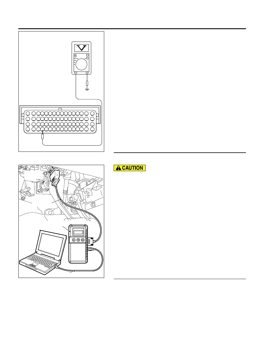
16 15 14 13 12 11 10 9 8 7 6 5 4 3
2
1
32 31 30 29 28 27 26 25 24 23 22 21 20 19 18 17
48 47 46 45 44 43 42 41 40 39 38 37 36 35 34 33
64 63 62 61 60 59 58 57 56 55 54 53 52 51 50 49
AA00
Special tool 64-pin
connector:
component side
(3)
Measure the voltage between terminal No. 61 and ground.
NOTE:
Vehicles for Canada, the headlight, taillight,
etc. remain lit even when the lighting switch is in "OFF"
position but this is no problem for checks.
a
.
Engine: warming up
b
.
Radiator fan: stopped
c
.
Headlight switch: OFF to ON
d
.
Rear defogger switch: OFF to ON
e
.
Stoplight switch: OFF to ON
⦆
Voltage should be drop.
(4)
Turn the ignition switch to the "LOCK" (OFF) position.
Q:Did the measured voltage drop?
YES:
Go to Step 3.
NO:
Go to Step 4.
STEP 3. Using scan tool MB991958, read the diagnostic
trouble code (DTC).
ZC501967
AC404789
ZC5019680000
MB991824
MB991827
MB991910
Data link
connector
To prevent damage to scan tool MB991958, always turn the
ignition switch to the "LOCK" (OFF) position before
connecting or disconnecting scan tool MB991958.
(1)
Connect scan tool MB991958 to the data link connector.
(2)
Start the engine and run at idle.
(3)
Read the DTC.
(4)
Turn the ignition switch to the "LOCK" (OFF) position.
Q:Is DTC P0622 set?
YES:
Replace the ECM. When the ECM is replaced, register
the ID code. Refer to GROUP 42B, ID Code Registration
Judgment Table <Vehicles with KOS> P.42B-12or GROUP
42C, ID Code Registration Judgment Table <Vehicles with
WCM> P.42C-8. Then go to Step 8.
NO:
It can be assumed that this malfunction is
intermittent. Refer to GROUP 00, How to Use
Troubleshooting/Inspection Service Points - How to Cope
with Intermittent Malfunctions P.00-15.
STEP 4. Check harness connector B-118 at generator
connector for damage.
Q:Is the harness connector in good condition?
YES:
Go to Step 5.
NO:
Repair or replace it. Refer to GROUP 00E, Harness
Connector Inspection P.00E-2. Then go to Step 8.
MULTIPORT INJECTION SYSTEM (MFI) <DIAGNOSIS>
13Ab-591
DIAGNOSTIC TROUBLE CODE PROCEDURES