Mitsubishi Outlander XL. Manual - part 343
STEP 1. Using scan tool MB991958, check VIN Information.
ZC501967
AC404789
ZC5019680000
MB991824
MB991827
MB991910
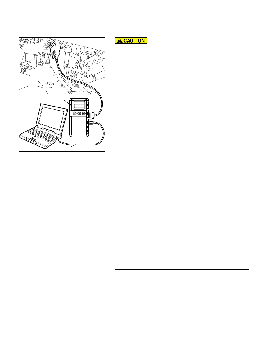
Data link
connector
To prevent damage to scan tool MB991958, always turn the
ignition switch to the "LOCK" (OFF) position before
connecting or disconnecting scan tool MB991958.
(1)
Connect scan tool MB991958 to the data link connector.
(2)
Set scan tool MB991958 to the coding mode for VIN
Information.
(3)
Turn the ignition switch to the "LOCK" (OFF) position.
Q:Has VIN (current) been written?
YES:
Go to Step 2.
NO:
Write VIN. Then go to Step 3.
STEP 2. Using scan tool MB991958, diagnose CAN bus line.
(1)
Turn the ignition switch to the "ON" position.
(2)
Diagnose CAN bus line.
(3)
Turn the ignition switch to the "LOCK" (OFF) position.
Q:Is the CAN bus line normal?
YES:
Go to Step 3.
NO:
Repair the CAN bus line. Refer to GROUP 54D, Can Bus
Diagnostics Table P.54D-189. Then go to Step 4.
STEP 3. Using scan tool MB991958, read the immobilizer
diagnostic trouble code (DTC).
(1)
Turn the ignition switch to the "ON" position.
(2)
Read the immobilizer-DTC.
(3)
Turn the ignition switch to the "LOCK" (OFF) position.
Q:Is the immobilizer-DTC set?
YES:
Refer to GROUP 42B, Diagnosis - Diagnostic Trouble
Code Chart <Vehicles with KOS> P.42B-18or GROUP 42C,
diagnosis - Diagnostic Trouble Code Chart <Vehicles with
WCM> P.42C-11.
NO:
Go to Step 4.
STEP 4. Using scan tool MB991958, read the diagnostic
trouble code (DTC)
(1)
Turn the ignition switch to the "ON" position.
(2)
After the DTC has been deleted, read the DTC again.
(3)
Turn the ignition switch to the "LOCK" (OFF) position.
Q:Is DTC P0606 set?
YES:
Replace the ECM. When the ECM is replaced, register
the ID code. Refer to GROUP 42B, ID Code Registration
Judgment Table <Vehicles with KOS> P.42B-12or GROUP
MULTIPORT INJECTION SYSTEM (MFI) <DIAGNOSIS>
13Ab-567
DIAGNOSTIC TROUBLE CODE PROCEDURES