Mitsubishi Outlander XL. Manual - part 341
ZK600387
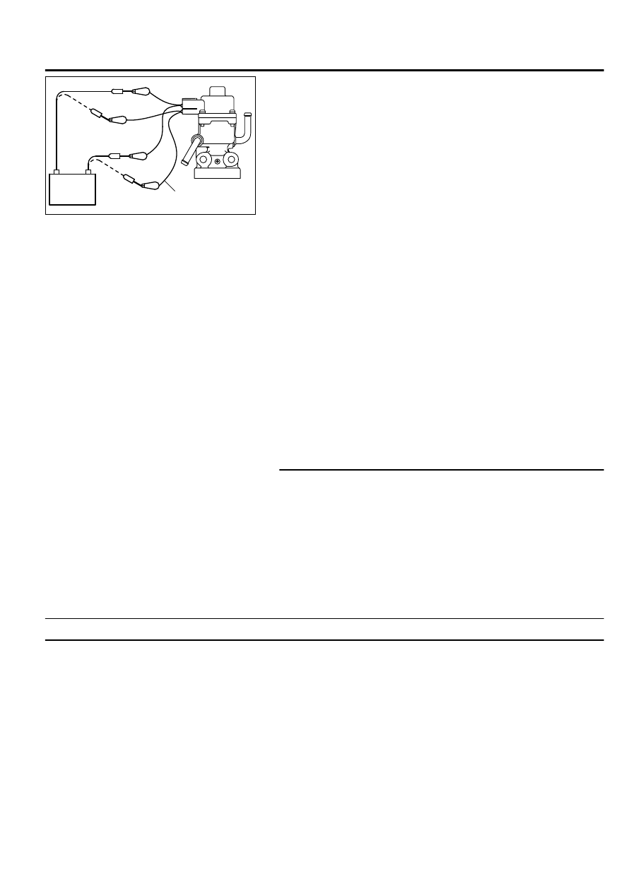
MB991658
Battery
AA00
(2)
Connect special tool MB991658 to the EGR valve. (All
terminals should be connected.)
(3)
Use the jumper wires to connect terminal No. 5 of the EGR
valve connector to the positive battery terminal.
(4)
Check to ensure that the motor operates when the terminal
No. 1 and No. 3 of the EGR valve connector are respectively
connected to the negative battery terminal using a jumper
wire.
⦆
Vibration should be present at each application of voltage
to test clip combination.
(5)
Then, use jumper wires to connect the terminal No. 2 of the
EGR valve connector to the positive battery terminal.
(6)
Check to ensure that the motor operates when terminal No.
4 and No. 6 of the EGR valve connector are respectively
connected to the negative battery terminal using a jumper
wire.
⦆
Vibration should be present at each application of voltage
to test clip combination.
(7)
Reinstall the EGR valve, using a new gasket, and tighten to
the specified torque.
Tighten torque: 23 ± 6 N·m [17 ± 4 ft·Ib]
Q:Is the EGR valve operating properly?
YES:
Replace the ECM. When the ECM is replaced, register
the ID code. Refer to GROUP 42B, ID Code Registration
Judgment Table <Vehicles with KOS> P.42B-12or GROUP
42C, ID Code Registration Judgment Table <Vehicles with
WCM> P.42C-8. Then go to Step 5.
NO:
Replace the EGR valve. Then go to Step 5.
STEP 5. Test the OBD-II drive cycle.
(1)
Carry out a test drive with the drive cycle pattern. Refer to
Diagnostic Function - OBD-II Drive Cycle - Pattern 3 P.
13Ab-8.
(2)
Check the diagnostic trouble code (DTC).
Q:Is DTC P0490 set?
YES:
Retry the troubleshooting.
NO:
The inspection is complete.
DTC P0506: Idle Control Sytem RPM Lower Than Expected
M11310100238USA0000010000
TECHNICAL DESCRIPTION
⦆
The amount of air taken in during idling is regulated
by the opening and closing of the throttle valve.
⦆
The ECM checks the difference between the actual
engine speed and the target engine speed.
DESCRIPTIONS OF MONITOR METHODS
Difference between actual and target idle speed is
over the specified value.
MONITOR EXECUTION
Continuous
MULTIPORT INJECTION SYSTEM (MFI) <DIAGNOSIS>
13Ab-559
DIAGNOSTIC TROUBLE CODE PROCEDURES