Mitsubishi Outlander XL. Manual - part 312


  Index      Mitsubishi     Mitsubishi Outlander XL - service repair manual 2007 year


Search            


Content   ..  310  311  312  313   ..


Mitsubishi Outlander XL. Manual - part 312


DTC SET CONDITIONS <Range/Performance problem - Alignment>
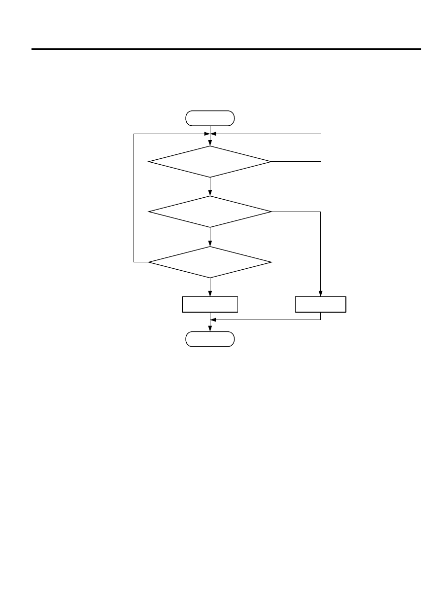
Logic Flow Chart

Start

End

No

Yes

Yes

Yes

No

No

Malfunction

Good

Continuous

failure for 2secs

Output signal

changes

Monitoring

conditions

ZK603760 AA00

DTC SET CONDITIONS

Check Condition

Engine speed is higher than 50 r/min.

Judgement Criterion

Normal  signal  pattern  has  not  been  input  for
cylinder identification from the crankshaft position
sensor signal and camshaft position sensor signal
for 2 seconds.

MULTIPORT INJECTION SYSTEM (MFI) <DIAGNOSIS>

13Ab-443

DIAGNOSTIC TROUBLE CODE PROCEDURES

DTC SET CONDITIONS <Range/Performance problem - Circuit continuity>

Logic Flow Chart

Start

End

No

Yes

Yes

Yes

No

No

Malfunction

Good

Continuous

failure for 2secs

Output signal

changes

Monitoring

conditions

ZK603760 AA00

Check Condition

Engine speed is higher than 500 r/min.

Judgement Criterion

Camshaft  position  sensor  output  voltage  has  not
changed (no pulse signal is input) for 2 seconds.

OBD-II DRIVE CYCLE PATTERN
Refer to Diagnostic Function - OBD-II Drive Cycle -
Pattern 24 P.13Ab-8.

TROUBLESHOOTING HINTS (The most likely
causes for this code to be set are:)

Crankshaft position sensor failed.

Camshaft position sensing cylinder failed.

Connector damage

Harness damage

ECM failed.


DIAGNOSIS

Required Special Tools:

MB991709: Test Harness

MB992110: Power Plant ECU Check Harness

13Ab-444

MULTIPORT INJECTION SYSTEM (MFI) <DIAGNOSIS>

DIAGNOSTIC TROUBLE CODE PROCEDURES

STEP 1. Check harness connector B-112 at camshaft
position sensor and harness connector B-10 at for damage.

Q:Is the harness connector in good condition?

YES:

 Go to Step 2.

NO:

 Repair it. Refer to GROUP 00E, Harness Connector

Inspection P.00E-2. Then go to Step 9.

STEP 2. Measure the sensor supply voltage at camshaft
position sensor connector B-112.

(1)

Disconnect the connector B-112 and measure at the harness
side.

(2)

Turn the ignition switch to the "ON" position.

ZK603373

1

2

3

AA00

B-112 Harness
connector:
component side

(3)

Measure the voltage between terminal No. 1 and ground.

Voltage should be between 4.9 and 5.1 volts.

(4)

Turn the ignition switch to the "LOCK" (OFF) position.

Q:Is the measured voltage between 4.9 and 5.1 volts?

YES:

 Go to Step 5.

NO:

 Go to Step 3.

STEP 3. Measure the sensor supply voltage at ECM
connector B-10 by using power plant ECU check harness
special tool MB992110.

ECM

ZK603234AA00

Body side harness 

MB992110

(1)

Disconnect  all  ECM  connectors.  Connect  the  power  plant
ECU  check  harness  special  tool  MB992110  between  the
separated connectors.

(2)

Turn the ignition switch to the "ON" position.

ZK603367

16 15 14 13 12 11 10 9 8 7 6 5 4 3

2

1

32 31 30 29 28 27 26 25 24 23 22 21 20 19 18 17

48 47 46 45 44 43 42 41 40 39 38 37 36 35 34 33

64 63 62 61 60 59 58 57 56 55 54 53 52 51 50 49

Special tool 64-pin 
connector:
component side 

AA00

(3)

Measure the voltage between terminal No. 9 and ground.

Voltage should be between 4.9 and 5.1 volts.

(4)

Turn the ignition switch to the "LOCK" (OFF) position.

Q:Is the measured voltage between 4.9 and 5.1 volts?

YES:

 Repair harness wire between the camshaft position

sensor connector B-112 (terminal No. 1) and the ECM
connector B-10 (terminal No. 9) because of open circuit
or harness damage. Then go to step 6.

NO:

 Go to Step 4.

STEP 4. Check for short circuit to ground between the
crankshaft position sensor connector B-112 and the ECM
connector B-10.

(1)

Disconnect the crankshaft position sensor connector B-112
and the ECM connector B-10.

MULTIPORT INJECTION SYSTEM (MFI) <DIAGNOSIS>

13Ab-445

DIAGNOSTIC TROUBLE CODE PROCEDURES

AA00

ZK603368

3

2

1

B-112 Harness
connector:
component side

(2)

Check  for  the  crankshaft  position  sensor  connector  B-112
(terminal No. 1) and ground.

Not continuity.

Q:Is the harness wire in good condition?

YES:

 Replace the ECM. When the ECM is replaced, register

the ID code. Refer to GROUP 42B, ID Code Registration
Judgment Table <Vehicles with KOS> P.42B-12or GROUP
42C, ID Code Registration Judgment Table <Vehicles with
WCM> P.42C-8. Then go to step 9.

NO:

 Repair it. Refer to GROUP 00E, Harness Connector

Inspection P.00E-2. Then go to Step 9.

STEP 5. Check for open circuit and short circuit to ground
between the crankshaft position sensor connector B-112
and the ECM connector B-10.

(1)

Disconnect the crankshaft position sensor connector B-112
and the ECM connector B-10.

ZK604089

16 15 14 13 12 11 10 9 8 7 6 5 4 3

2

1

32 31 30 29 28 27 26 25 24 23 22 21 20 19 18 17

48 47 46 45 44 43 42 41 40 39 38 37 36 35 34 33

64 63 62 61 60 59 58 57 56 55 54 53 52 51 50 49

1

2

3

B-112 harness connector:
component side 

B-10 harness connector:
component side 

AA00

(2)

Measure  the  resistance  between  the  crankshaft  sensor
connector B-112 and the ECM connector B-10.

Should be less than 2 ohms.

a
.

Connector  B-112  (terminal  No.  3)  and  Connector  B-10
(terminal No. 14).

b
.

Connector  B-112  (terminal  No.  2)  and  Connector  B-10
(terminal No. 30).

AA00

ZK603370

1

2

3

B-112 Harness
connector:
component side

(3)

Check  for  the  crankshaft  position  sensor  connector  B-112
(terminal No. 3) and ground.

Not continuity.

Q:Is the harness wire in good condition?

YES:

 Go to Step 6.

NO:

 Repair it. Then go to Step 9.

13Ab-446

MULTIPORT INJECTION SYSTEM (MFI) <DIAGNOSIS>

DIAGNOSTIC TROUBLE CODE PROCEDURES


Content   ..  310  311  312  313   ..